A couple of issues are:
Housing in the UK
We are desperately short of houses, and a lot of the stock we have is poor, energy wasteful and decrepit.
But houses are not being built.
Current government proposes to increase house building by relaxing the rules, and at the same time as pushing a “localism” agenda for communities to manage their own environment, has legalised land grabs by speculating developers.
Two aspects of this which are the most damaging are
- Councils receive from central government money for every new house built, effectively this amount is a bonus of the council tax value of the next 6 years. This encourages them to freely give planning permissions t to the most housing they can get away with, with little or no consultation with communities that elect them.
- Planning policy says quite clearly that permission cannot be refused if the development is “sustainable”. The definition of sustainability is wide open to abuse, and developers are very good at filling gaps by “mitigation” arguments. Thus councils can not refuse approvals, or developers will go to law and sue them to reverse decisions - at tax payer’s cost.
The result of all this is that councils are giving more and more approvals, but houses are not being built, because land assets are inflated (as developers buy land cheap and get planning permissions which increases the value), This looks good on the developers balance sheet, but means that they cannot build houses at a cost (= land + house build cost + council costs for serves + profit) that people can afford.
Government initiatives to tempt people into taking unaffordable loans (75% from banks and 20% short term from government) are a false stimulus. They still cannot afford the repayments, even if the government part is interest free, and they will get into uncontrolled debt.
So planning approvals are given, without community support or consultation, land assets go up, and NO houses get built.
HS2
HS2 proposals beggar a big question about what kind of society we want to build. The sums are so great (£50bn / 25M tax payers = £2000 each) that one can truly question the advantages of transporting thousands of people at very high cost between city centres and gaining just 1/2 hour to do so.
The way our society is organised today is increasing and increasing “run about”, more and more people are travelling to work, traveling to meet each other, traveling... yet 90% of businesses in UK have less than 10 employees.
To serve communities and those 90% of small businesses we have to find a way to cut traveling and invest to grow locally.
That is what we need to spend £50bn on:
- Housing and business planning
- Business premises and tax reductions
- Local transport infrastructure
- Communications, or broadband to give “virtual office” capability across the UK.
- Electric, autonomous delivery vans, and other automated infrastructure
- More beautiful places to live
Politics and government
We have to accept the state of humanity. Just chose how do we want to live with it? Living in UK is very different to living in the Sahara or in Syria.
We have to accept that the a lot of humanity is, in western eyes, in-humane in many ways. Not to accept this, and leave people to evolve by themselves, has created social upheavals, law making, wars etc etc as those, you could almost call them “do gooders” push to construct a society in which ”decent” people can live.
And even here in UK we have inverted politics. Today politicians do not consult with the people they represent, then take these views to parliament, but conversely they make up policies, publish manifestos, ask for a vote then pass laws, dictating back to the public what should happen. And in many cases law making outside the very manifesto they were elected on, with no community input, except from lobby groups. And even these are coming under attack.
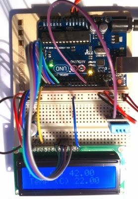
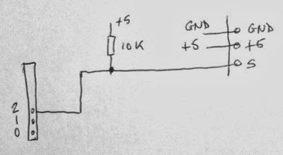
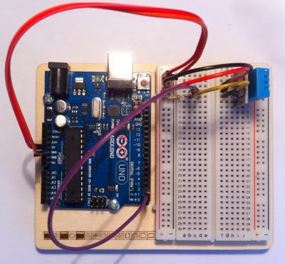
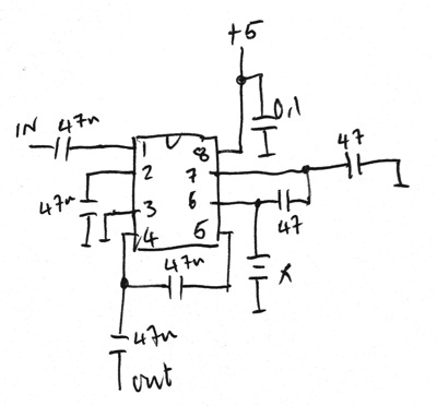
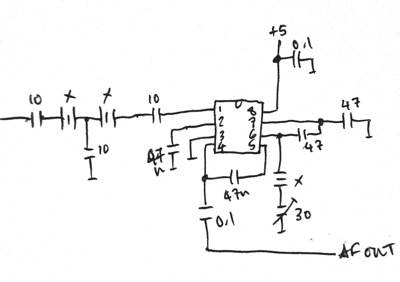
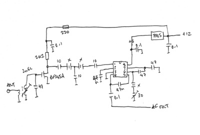
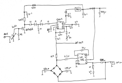
 The code
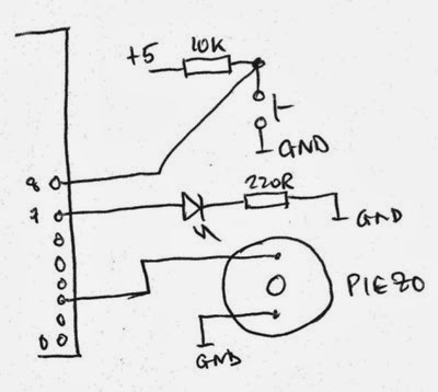
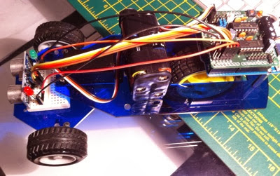
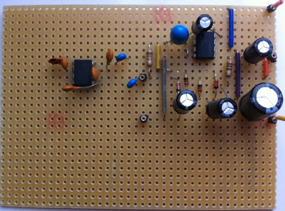
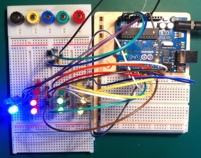
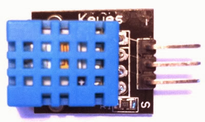
 There are now four I/Os, the steering servo, a light detector under the from of the robot, two LEDs (red and green) which show the steering direction and the sonar detector for obstacle detection.