I need a list of where I am with all my projects. So here it is
CONCEPT - 2015
1. DDS & RTC shield. Si5351 DDS, outputs G0 (CLK0), G1 (CLK1) & 74AC74 for I/Q outputs. Eagle SCH & BRD files OK, PCBs made
2. SDR RX shield. FST3251 QSD & TLV6424 Amp. 40m input filter. I/Q inputs from DDS & RTC shield. Eagle SCH & BRD files OK, PCBs made.
BASIC - 2016/7
3. VFO-Simple shield. A 40m Varicap tuned VFO for Intermediate students to build. Eagle SCH & BRD OK, PCBs in production.
4. DCRX shield. NE602/SA612 mixer & LM386 Amp. 40m input filter, input from DDS & RTC. Eagle SCG & BRD OK, PCBs made.
5. DCRX_WIDE shield. NE602/SA612 mixer & LM386 Amp. Wide band 50R input matching. Use external BPF for each band. Eagle SCH & BRD OK. PCBs not made, as PCB above can be used.
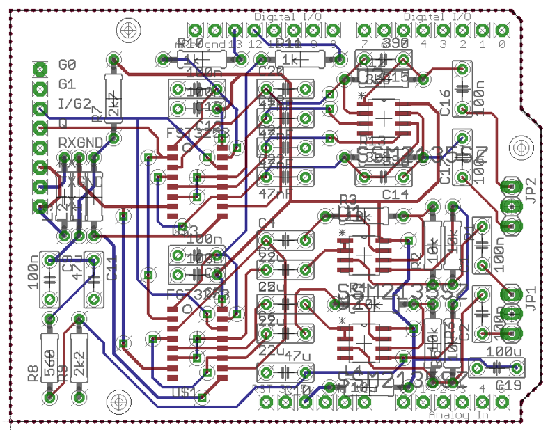
6. QRP_RIG_BASIC shield. Complete Rig RX & TX. FST3251 QSD & QSE, SSM2135 for audio ccts. Wide band input, use BPF for band selection. Eagle SCH & BRD OK. PCB in production.
7. RF_METER shield. Input 40dB attenuator, AD8307. Output 20MHz LPF ERA-2SM buffer. Eagle SCH & BRD OK, PCB made
8. RETURN_LOSS shield. Antenna analyser bridge, circuit under development. Proto done, software shaky
9. WSPR_PA. No design done, may use commercial 2W wide band amp driven by DDS & RTC via BPF, need LPF on output? Could use for QRP_RIG if arrange TX/RX switching...
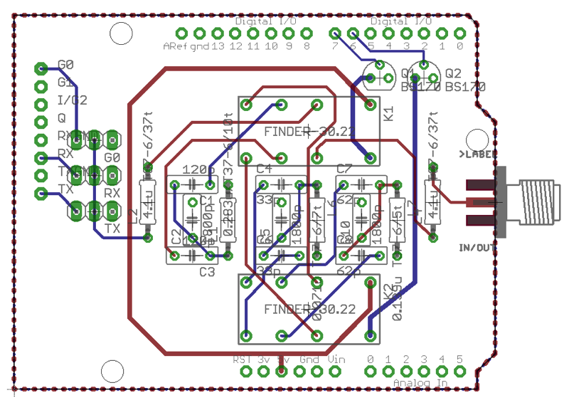
10. BPF_BASIC shield. Design done for 40, 30 & 20m BPF, 2KHZ BW Chev. Eagle SCH &BRD OK. PCB in production. Tested, doesn't work abandoned Replaced by 3xLPF shield
Future
External PA 20-50W to be defined, stand alone with internal PSU & LPFs, maybe Antenna auto tuning?
Friday 23 December 2016
BASIC Tech Group - MyNews 12 - All my hardware shieldprojects update
BASIC Tech Group - MyNews 11 - Final BPF, QRP_RIG & RF METER PCBs
Well I've taken the plunge, or in other words ordered my Christmas present! I have ordered the PCBs for three of my projects. Yes three!
The BPF-Basic - note: this abandoned as doesn't work...
This is a set of three Band Pass Filters for 40, 30 & 20m bands. Intended for use both for the front end for the QRP_RIG TXRX, the DCRX Direct Conversion RX, or any other input/output that needs a BPF on one of the bands.

The QRP_RIG-Basic a single board TXRX
This has been on of my long term aims, to build a single board Arduino shield which is an SDR based TX and RX able to work over a wide band of frequencies - is it a broadband design, the working frequency is determined by the DDS input and BPF on the input/output.


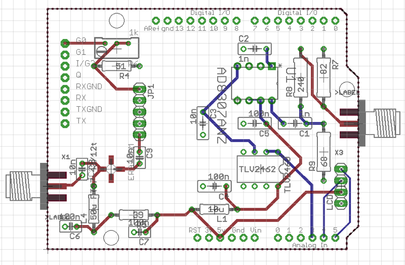
An RF METER-Basic - schematic updated, see later blog
A sensitive RF Meter with RF output also from the DDS via a LPF and buffer amplifier
This is one of the most useful measurement tools for an amateur shack, able to measure RF inputs, to 50R impedance, from -60dBm to more than +20dBm. And an RF source at around 1-10mW programmable by the Arduino from 100kHz to 20MHz.


Let's hope these work first time as the PCB costs are going up as the UK Pound falls - they come from Eurocircuits in Belgium, one fo the few PCB makers that accept Eagle "BRD" file inputs.
Wednesday 21 December 2016
BASIC Tech Group - MyNews 10 - ADF4351 project, LPFs, RF Meter update
Wow! Says Gordon (G4EBF) who is building a 35MHz - 4.4GHz VFO based on the ADF4351, to program this he is learning about the Arduino. Today he says he he has got the Arduino IDE installed on his PC, has configured it, and has loaded his first program to Blink and LED. Well done, that's the way everyone starts with the Arduino, and that's what we did at BARS during the Concept SDR project last year.
I have received a set of LPFs from LanguageSpy and have put the values of the components into LTSpice to see what they yield.

And this is the response in LTSpice for the 20m filter:
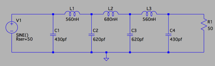

Quite a nice response and sharp cut off, with a little bit of ripple in the passband.
I have decided to order their 17m filter and use this in my RFMETER design to filter the Si5351 DDS output and remove higher harmonics. The RFMETER design is now complete.

I will be ordering the PCBs (10) very soon.
Tuesday 20 December 2016
BASIC Tech Group - MyNews 9 - New WSPR sketch 40m
Finished the coding of a new WSPR sketch, based on the WsprMessage.h library written by John Newcombe and used and published by M0XPD.
I built this into a library module that can be included in the Arduino sketch. This sketch uses the LCD display routines of my previous WSPR program, but is simplified as it has a fixed repeat interval for transmission of 2sec and a fixed frequency of 7040.1kHz (the previous sketch allowed a Rotary Encoder input to change the frequency and the repeat interval - an upgrade would be easy to do to implement these features).
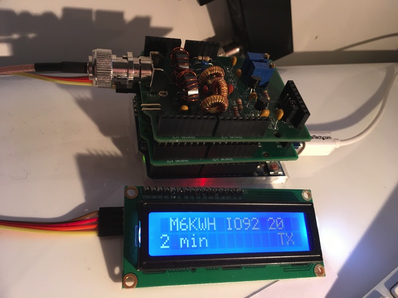
Photo shows the 2 shield stack on top of the Arduino UNO, the DDS and a LPF shield
As usual there is an option to define the LCD I2C address as some displays use 0x27 while others use 0x3F.
The system timing is provide by an RTC (DS3231) module on the Si5351 DDS shield. This can be set by a separate Arduino sketch (at the bottom below) to the correct time, which must be good to 1second.
The code to transmit is also hard coded into the sketch, in my case it is currently "M6KWH IO92 20". The WsprMessage.h library encodes this into 162 elements of value 0, 1, 2 or 3 in the array WSPR_Message{ ].
The WSPR system has a 4 level FSK modulation, with frequencies spaced by 1.4548Hz! This is trick to do, and what this sketch does is to define a frequency shift for each element in an array delta[ ]. The data is the frequency shift of each element to the nearest cHz (0.01Hz) as this is the resolution that can be generated by the Si5351 and the si5351.h library. All frequencies are defined for this library in cHz. So, for example, the variable WSPRFreq = 7040.1kHz is 704010000cHz. All frequency variables are uint64_t size.
The newer LiquidCrystal_I2C.h library is used (from HobbyComponents.com) which has a different set of calls, in particular the initialisation is done with lcd.begin(), not the previous library call lcd.init(). And the new si5351.h library is also used which changed some of the calls to program the SI5351 chip. If you are going to use this code, make sure you Google and use the new version of the libraries.
I have put a Zip file of all these libraries here.
Download the code for WSPR and for RTC time setting
WSPR_40M-Basic
RTCSET-Basic
BASIC Tech Group - MyNews 8 - Update LPF, QRP_RIG & BPFs
A few progress reports on the Arduino projects:
1 - LPFs ordered from languageSpy web site for 40, 30 & 20. Maybe incorporated into the buffer amplifier using an ERA-2+ MMIC, on the antenna bridge and/or RF Meter shield designs...
2 - PCB design for the QRP-RIG i done, awaiting checking carefully..
3 - Band pass filters designed for BPF shield, 40, 30 & 20m, 2MHz BW Chev 0.1dB ripple.


More news coming when QRP-RIG & RF METER PCBs finalised and ordered.
Slides of current BASIC Arduino projects is here.
Monday 12 December 2016
BASIC Tech Group - MyNews 7 - Harmonics from Si5351 DDS?
Using a Si5351 module from Adafruit (Kanga) as a VFO for my Direct conversion RX and for my WSPR TX.
The WSPR TX is transmitting on 7040.1kHz with the "M6KWH IO92 20" message..

I have the RX connected to my Macbook via a Startech A/D convertor running at 48kHz sample rate. The on the Macbook I ran two programs, Argo.exe a Windows program running un Wine emulator, and WSPR program native to the Mac.
These are what the two prgrams show when the RX is tuned to 7038.6kHz.

and

What you can see here is that a lot of harmonics or side lobes are being received. I don't know if these are being transmitted by the WSPR TX or if they are spurious reception by the RX. What I get on the WSPR readout is two IDs, one at the nominal 7040.1 frequency (at 100 on the scale) and another which is 100Hz above. These two and others can be seen on the Argo screen.
I have tried all sorts of software changes but not found the cause...