Thursday, 31 December 2020

Building a QCX+ CW transceiver

I have ordered a QCX+ transceiver from QRP-LABS.  But before it arrives I decided to take a look at the RX circuit, This is in three parts

1. A basic Tayloe quadrature detector, fed by RF signals with 0/90deg phase shift from a programmed Si5351 synthesiser. (See here for an example Arduino program snippet on how to do it)

The QCX+ RX frequency is set 700Hz lower than the TX frequency to give a 700Hz beat. This uses the Upper Side Band for reception. The VFO A display always shows the higher TX frequency.

2. An AF phase shift network, tuned to have a 0/90deg phase shift at a narrow band of audio frequencies, nominally around 700Hz +/- 100Hz.

3. An AF filter with a peak response at 600-800 Hz.

1. DETECTOR

Some info about generating 0/90 deg phase shift RF I & Q signals is in my blog in Digital SSB, April 2020 posting. With an Arduino code listing for this type of application here. I think QRP LABS have published their "Arduino" code for the QCX+ also. 

More info about SDRs and the Tayloe detector is here (pdf)

2. PHASE SHIFT NETWORK

To be analysed. But its very simple and only splits the 0 & 90deg I & Q signals over a narrow band of audio frequencies, no good for SSB reception...

3. BAND PASS FILTER

The first discussion and LTSpice simulation is of #3,, the audio filter. The result (pdf) and spice (".asc" file) are here. As you can see this is an effective CW filter at the popular listening AF of 600-800Hz. The actual audio frequency, which is simply the TX-RX offset frequency can be set in a menu item, but of course must lie in the BW of the hardware filter!


MENUs - here is a summary of the menu.

QCX MENUs


SELECT___


1 Preset S

   1.1 - 1.16 freq presets


2. Messages S

   2.1 send interval

   2.2 reeats

   2.3 - 2.14 messages


3. VFO S

   3.1 mode A, B, SPLIT

   3.2 VFO A default

   3.3 VFO B default

   3.4 Tune rate default

   3.5 RIT default

   3.6 RIT rate default

   3.7 CW-R ON|OFF mode, OFF RX is USB

         TX-OFFSET, ON RX is LSB TX+OFFSET

   3.8 CW OFFSET nom. 700Hz


4. Keyer S

   4.1 straight, IAMBIC A, IAMBIC B, Ultimatic

   4.2 keyer speed WPM

   4.3 keyer swap dit/dah ON|OFF

   4.4 keyer weight, 500 = 1 dit, 3 dah, 7 word

   4.5 auto-space ON|OFF 3xdit between chars

   4.6 semi QSK ON = semi-QSK

         OFF = full QSK break-in

   4.7 practice ON = no TX, OFF = TX

   4.8 sidetone Hz nom 700Hz

   4.9 sidetone vol

   4.10 straight mode TIP, RING, BOTH 

        3.5mm connections


5. Decoder S

   5.1 Noise blanker (ms)

   5.2 speed avg

   5.3 amplitude threshold 

   5.4 enable RX decode ON|OFF

   5.5 Enable TX decode ON|OFF

   5.6 enable edit ON|OFF - key entry of msgs

   5.7 VA/SK display ON|OFF


6. Beacon S

   6.1 mode OFF, CW, WSPR, FSKCW (QRSS)

   EXIT_ = STOP

   6.2 Frequency TX freq 7040000 - 7040200

   6.3 frame WSPR repetition rate WSPR (min)

   6.4 start time past hour

   6.5 WSPR call _M0IFA (6 char)

   6.6.WSPR locator IO92, or set by GPS

   6.7 WSPR power (dBm) 5W = 37dBm

   6.8 set time RTC, or set by GPS


7. Other S

   7.1 double click sets button press timing (ms)

   7.2 battery ON|OFF display voltage icon

   7.3 battery full detect level nom. 13,800 mV

   7.4 battery step nom 1,000mV/bar

   7.5 cursor blink ON|OFF

   7.6 S-meter ON|OFF display

   7.7 S-meter step nom 100, sets sensitivity

   7.8 custom splash set own power-up screen

         from messages 11 & 12

   7.9 clock ON|OFF display

   7.10 delimiter char nom “,”

   7.11 factory reset sure? rotate to 17


8. Alignment S

   8.1 align frequency set to centre of CW band

   8.2 I-Q balance frequency phase shift at 700Hz

   8.3 phase low frequency phase shift 600Hz

   8.4 phase high frequency phase shift 800Hz

   8.5 reference frequency 

         27,004,000 Hz Si5351 clock (GPS cal)

   8.6 system frequency

         20,000,000 MCU clock (GPS set)

   8.7 peak BPF, audio amplitude at 700Hz

   8.8 I-Q balance reference frequency 700Hz

         to unwanted sideband (LSB)

   8.9 phase low —ditto - 600Hz

   8.10 phase high — ditto— 800Hz

   8.11 calibrate reference oscillator,

           activate GPS calibration, waiting, 6sec

           3-2-1 closer calibration

           0 OK calibrated

   8.12 calibrate system oscillator,

           —ditto—


9. Test equipment S

   9.1 DVM input 0-20V nominally, jumpered 

         to battery voltage

   9.2 RF power 0-5W

   9.3 audio ch 1, audio amp input

   9.4 audio ch2, phase null output

   9.5 frequency of counter input to

         timer 1 of MCU (5Vmax) 

   9.6 signal generator CLK0&1 3.5kHz to 200MHz


Save settings (to EEPROM) S


EXIT_

Monday, 14 December 2020

Mac Mini setup for SDR FDM-SW2 (Windows) and WSJT (MacOS)

I am running the ELAD FDM-SW2 SDR software under Parallels and Windows 10 on my Mac Mini, 

FDM-SW2 under Parallels & Windows 10

This is the setup I have for signal routing to get everything to where it is supposed to be. I have connected all three USB connection on the FDM-DUO to the Mac Mini. 

SOUNDSOURCE

I am using SoundSource  to direct the sound coming from FDM-SW2 through Parallels to a Bluetooth LS.


In this way the specific audio output of Parallels is directed to the Bluetooth "Anker Soundcore" LS. (the BT connection has to be "Connect" in MacOS for this, of course).

WINDOWS 10

Next we have to set up FDM-SW2 SDR software running under windows. We need not only to set up the audio, but also switch one of the USB inputs to Windows. This is the FDM-DUO "RX" connection to deliver the SDR IQ data. This can be done in the Widows 10 desktop by using the Parallels tools, opened by sliding the cursor to the top of the window.


Select the USB Icon and chose the FDMDUO USB FW v4.9 connection to Windows. FDMDUO has an odd naming convention for its USB connections, they correspond to

- FDM-DUO Audio v1.04 = TX connector, audio IN and OUT digital 48kHz
- FDMDUO USB FW v4.9 = RX connector, for FDM-SW2 software
- FT232R USB UART = CAT connector , ASCII commands IN and OUT for CAT control

why ELAD can't name them sensibly is a puzzle for another day.

PARALLELS

Parallels is set up to send its audio to "Default" as it is captured and re-directed by SoundSource (above). 


FDM-SW2

In FDM-SW2 chose "SET" and the Audio tab, and chose Soundcard and output device "Speakers (High Definition Audio)" which is what Parallels calls its audio output


WSJT

WSJT on a MacOS desktop

To run WSJT at the same time but under MacOS, Open it in a new desktop and  under WSJT > Preferences chose the Audio tab and set a direct connection to the USB audio to/from the FDM-DUO TX connection (it is not only TX input as the marking would suggest, but also RX digital audio output!)

SO...

After all that, phew! You can use WSJT and FDM-SW2 SDR at the same time. Both programs will issue CAT commands, if you set the frequency in WSJT to for example 7074.0kHZ for 40m, then the central frequency of the FDM-DUO is set to this and this is what FDM-SW2 display shows as the RED frequency (it will also set it to Upper Side Band). Use the yellow, green or blue receivers set to LSB to transmit SSB on the lower bands.

SSB TX

To transmit on SSB you must set up the FDM-DUO to accept USB or MIC audio input by Menu 32 TXIN set to AUTO. Then PTT will trigger with the microphone as usual. WSJT will also PTT using RTS signal on the CAT connection.

AND THE BEST BIT, AND THE WORST BIT

Funneling the output audio through SoundSource has a big advantage. Voice communications occur in a narrow band of audio frequencies based around 500-2500Hz. SoundSource has the ability to apply audio filters to any application channel. And this can be used to filter the output of Parallels to the Bluetooth speaker using a 10 band EQ. This makes a dramatic difference to the capture of weak voice signals! I am testing if the same routing can be done for an externally connected microphone feeding audio into Parallels an don to FDM-SW2 on transmit...


Of course FDM-SW2 has also an audio processor with EQ, VOX and Compression for trasnsmit, would that was easier to setup and use!!! It can take its input from a USB or normal microphone plugged into the Mac Mini. And feed its output to the TX digital input of the FDM-DUO radio via the TX input. But then you cannot use TX & CAT for WSJT FT8... sigh.

Even on a pure Windows setup getting WSJT to work is a mess of different softwares needed to redirect the audio to/from FDM-SW2 and the CAT control from WSJT... not a pretty site.

Saturday, 12 December 2020

Another go at WSPR

 I thought to pass the time I would have another go at WSPR. I have a simple Arduino sketch WSPR_FIXED written to program an Si5351 synthesiser to transmit WSPR on 7040.1kHz (1500Hz audio from an RX tuned to 7038.6kHz). I have also a very simple two transistor RF amplifier which can generate 0.5-1W output.

I tested it using my ELAD FDM-DUO receiver, coupled to my Mac Mini running WSJT software.

However the output of to Si5351 CLK1 is much to large to connect to the amplifier input! So in an odd way I must use a -30dB attenuator, then amplify it back up! Here's the scheme of things

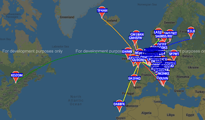
I am using my regular small 60cm loop antenna (simply because no outdoor antenna are permitted at my QTH). And here is what I got in the last 24 hours (from WSPRnet site)


I call that pretty much amazing for 500mW and the small loop antenna. Toronto, Iceland, Canaries, St Petersburg!!!

Sunday, 6 December 2020

Pixie challenge

 A couple of years ago I ran a light-hearted challenge at our radio club. Called the "Pixie Challenge". 

The Challenge

I sourced and provided a kit of pieces including the famous Pixie CW transceiver (fixed 7023kHz), all the plugs and sockets and a small audio amplifier/speaker.

The kit.
The challenge was in two parts:

1. Build the Pixie kit and get it working. To prove this club members had to receive a CW Beacon transmitted from my programmable VFO - an Arduino Nona and a Si5351 synthesiser (See here) which was transmitting "CQ PIXIE K" at 10 words per minute. (CW_BEACON Arduino code here)

2. Make a CW QSO between two Pixies, passing a secret code  known only to each individual.

This was the set up showing the programmed VFO and the Pixie


Ironically the prize, a soldering iron, was won by a new, non-licenced member of the club! But the most experienced "old boy" ruined his kit by soldering the transistors in backwards.