Tuesday, 11 January 2022

SDR_TFT Software defined radio TRX with TFT Display

 WORK IN PROGRESS

I am at the thinking stage and fiddling about stage, I have been inspired by the keithSDR project and N6QW to work out my own Teensy based SDR Transceiver.

Hardware

The hardware is made up of 

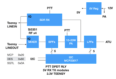
- a QRP Labs SDR receiver module, covering 1-30MHz. Synthesiser input @ x4 frequency, output Audio IQ to

- a Teensy and Audio Adapter, and connected display, encoder, PTT switch, band & sideband buttons, SWR bridge inputs

- a home grown RF & AF IQ mixer, a set of BPFs, a QRP Labs 10W PA and a set of LPF, covering 5 bands 80-40-30-20-15. This will be the most difficult part of the project, why doesn't someone make a module for this?

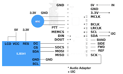
Teensy 4.0 connections


RF block diagram, plus an SWR bridge...

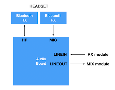
Audio adapter, can I do Bluetooth audio to a headset.
a huge software challenge?


Self developed SSB RF generation
Tough!


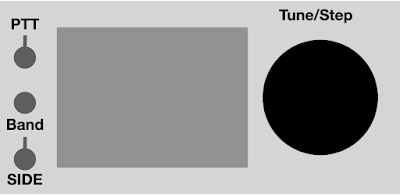
Controlling the SDR are

- a PTT DPDT switch or relay (5V for RX & PA, 3.3V for Teensy PTT)

- a Band select button

- a USB/LSB sideband button

- a rotary encoder for Tuning

- a frequency tuning step button (on encoder)

with an 2.8" or 3.5" TFT colour display (ILI9341 or ILI9488)

One thing that has not, yet, been thought about is CAT control of the transceiver. If I do it I will chose the more simple Kenwood ASCII command approach.

Dream layout KISS

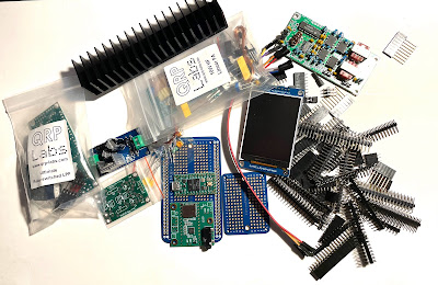
Starting to gather the parts

10W PA, RX, Display, relay kit, 5V PSU, Teensy & Audio board, headers

SWR Bridge

Make the easy things first

The SWR Bridge

LPF module

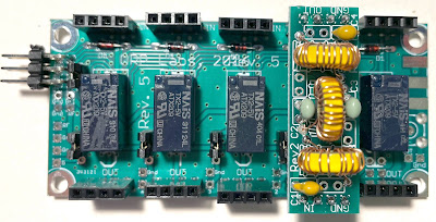
One of the two QRP Labs modules (Mixer BPF & PA LPF) , here with a 20m LPF mounted

LPF module, sockets are not as 
wobbly as this photo seems to show!

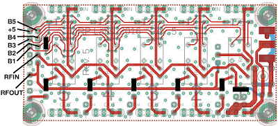
Connections, using 2 x 5 pin header for B1 to B5 & +5
Links shown in solid black

I will need to build some BPFs as I want to design the RF IQ mixer first, then probably the display layout next so I will need the Teensy. In the mean time I want to try out the PA with my QCX to push up the power on WSPR...

The QRP Labs 10W PA

In build

Teensy & Audio Adaptor

In development. 

My T4 does not work - may have blown it up, electrostatics? Playing with T3.2 for screen function developments (see below). I also will need a new audio adapter, T4 if I replace it or T3.2 if not...

Power supplies

A small 12V/3A SMPS and a 5V regulator, 3.3V comes from the Teensy. May put 12V outside and only 5V reg internally...

Power supply 12V/3A and 5V regulator

Software

The basic processing plan is this - a simple solution I admit,  for now.

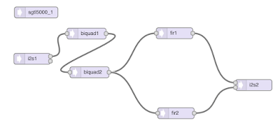
TX
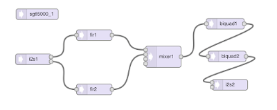
RX

In both chains there are two Hilbert audio BPF with +45 and -45 deg phase shifts, and two Biquad filters of 300-2.3kHz to sharpen up the overall filtering. Choice of sideband is made by software swapping Hilbert +45 and -45 in the chains. I hope to use 96kHz audio BW, may have to modify the RX. How do I get the audio adapter SGTL5000 to run at 96kHz rather than 44.1kHz???

PTT will switch the audio configurations above, and also chose the input/output configuration. On TX MIC & LINEOUT, on RX LINEIN & HP OUT. Sideband switch will swap the Taps +/-45 of the FIR filters. The frequency is handled by an interrupt routine from the rotary encoder, and the frequency step is a button input, as is the band/start frequency.

These audio components and pathways are defined using the new Open Audio F32 library (a 32 bit floating point audio library for the Teensy). An S meter will show the rms signals and if am clever the peak also, and an FFT will display a spectrum and water fall over a range +/-48kHz of the centre frequency.

Screen layout

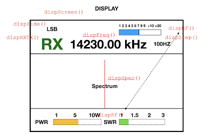
This is my first proposal, fairly simple with the functions currently being written to handle each part shown. I plan to use a low cost ILI9341 2.8" or 3.5" screen.

Proposed display

The basic underlying layout is initialised by "dispScreen()" and the items are displayed by dedicated functions. Not that "dispRF()" handles all three of Power, SWR and S meter bar charts. Others are

- dispRxTx(ptt), for the large RX or TX signs
- dispSide(side), for the USB/LSB sideband
- dispStep(freqStep), for the tuning step 10Hz - 10kHz

- dispFreq(freq), for the frequency in kHz - updated by encoder interrupt

- dispSpec(?input), for the spectrum - free running
- dispRF(SLevel, power, swr), for the S meter (RX), power and SWR meters (TX) - free running

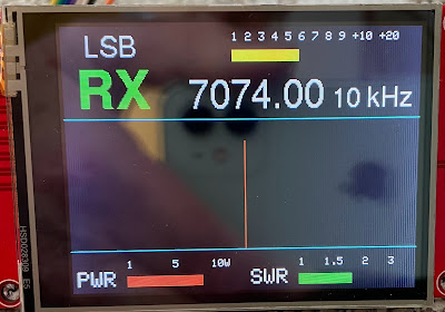
Here's the current screen

Draft screen layout

Trial on Teensy 3.2

A test display sketch using Adafruit GFX library and Adafruit ILI9341 driver works on an Arduino UNO, but it is very slow to update the display. It also works on a Teensy 3.2 much faster.  I will continue development for the Teensy 3.2 which I have previously used as a stand alone IQ SSB decoder with an Elektor SDR RF  front end. And look to moving to the Teensy 4.0 later.

Test sketch MYSDR_TEST and Tft.h Header

As far as the arrangement of the software is concerned. I have followed my previous style and am putting most of the detail functions (dispFreq() etc) in a separate Tft.h header file and the SDR funcitons (setPtt() etc) in a separate Sdr.h header. This much simplifies the main sketch code. Current MYSDR_TEST and Tft.h can be found here, but updates are quite frequent.


Thursday, 30 December 2021

QDX arrives - tomorrows Digital Transceiver, today

 QDX Digital Transceiver

I have blogged before, just down a bit, about the remarkable QRP Labs design for a digital transceiver for 80-40-30 & 20m. This design is a conventional SDR receiver, including digital sythesised frequency control, IQ audio to digital I2S codec, software filtering & decoding of USB signals and finally a "sound card" USB interface to your PC or Mac. [more below]

It is the transmit side which is very innovative. The digital USB audio from your PC has it's frequency measured, very fast and very accurately, this digital timing then sets the output frequency square wave of the synthesiser. The resulting RF frequency is amplified digitally and in a class "D" output amplifier. Giving an output of up to 5W across HF bands.

Also included is a CAT serial port implemented on the same USB socket, so your PC sees two ports, audio in/out and serial in/out. These can be directly selected in WSJT-X for FT8, WSPR or other digital modes.

My kit has arrived

QRP Labs were very kind to put me on the early release shipment list for the next batch of QDX kits and mine arrived yesterday. This is it

QDX kit, that I have started to build.
It is sooo small. Fits in the palm of your hand

The build

1. I read the documentation twice. Very detailed very clear. Seems most of the build is winding toroids. Anyway I have started as instructed to mount the very small capacitors. And I have had a lot of difficulty reading the tiny values printed on them. I mounted 7 and have now taken a break.

2. Finally finished the caps, by a process of elimination as I simply could not read the writing on final value. Hope OK...

3. Moved on and mounted the RFCs & diodes - one diode was cracked at the end where the wire comes out I hope it performs OK.  I then mounted the PA transistors and bolted them down, easy.

4. Now the coils. I have wound a few toroids in my time, but I hate it and feel like a novice every time I start. I have chosen the 12V operating power supply so wound the PA transformer 3:2. And I lost count so many times when winding the 19-30-36-41 turn input BPF inductor. But finally arrived here:

First components fitted and
started on the coils

5. So on with more and more toroids. I do wonder if QRP Labs could find a source of pre-wound toroids as this is the most tedious part of the kit construction. But then may be it would be too simple. Seven toroids to go... six for the transmit LPFs 80-40-30/20m and one for the balanced RF input

6. At last got all those pesky LPF coils wound and fitted. I am always scared at this point that I have got bad soldered joints and/or wrong number of turns on the coils. 

LPF coils mounted, did I get the turns right?

7. Seems very little 0.33mm wire left for the last transformer T2. Just starting measuring it now. Well I did not by a long way have enough 0.33mm (AWG 28) wire left, 3 x 20cm... so I had to use some 0.28mm (AWG 32) which I had in my components draw. What a faf to twist these three wires, then wind 10 turns, then a faf to identify the correct connections. At last to insert them, finally to solder them. They are very very close tother components so great care is needed. But I must praise the documentation for its calm and clear instructions, without which  I would have gone mad.

8. And now to finish up. USB, 12V power and Antenna sockets mounted. Finished. And here it is

I am proud of myself. A neat tiny 5W transceiver!

9. Now to try it out. Think I will box it first as this is easy and straightforward, and I can easily unmount it if anything is wrong, So I did

Boxed QDX, case ground connection not shown 
here (see comment below)

Testing

First let's get it connected. Plug in the antenna (an AL-705 loop and Mat-125 ATU). Whoops, the op manual says, "DCPower: use a regulated well- smoothed DC supply of not more than 12V". My shack is all running on a 13.8V supply but I think I have a home grown 12V supply somewhere in a dark pullout draw, I look it out. Yes, here it is, check the voltage, OK 11.8V. Last use this fancy new, posh, white  USB B to USB C cable that I bought for the purpose to connect the QDX to my MacBook Air. 

Software - MacOS

No drivers to install as the Mac has drivers for all main uses, digital audio and serial comms included. I have the latest version of WSJT-X installed which I normally use for FT8 with my ELAD FDM-DUO transceiver.

WSJT-X - preferences

1. Radio setup: I chose Kenwood TS-480 for the correct CAT commands and the QDX serial port (mine was called "/dev/tty.USBmodem101") should be set at at 8-1-N, the baud rate can be left at 9600 as the USB virtual port does not need this to be set to a particular value. PTT should be set to use CAT commands.

2. Audio setup: For input and output I chose the "QDX Transceiver"

I set the WSJT-X PWR slider to max as the QDX converts any input to square waves and the output is not dependant on the audio input level, only the power supply of 12V to the switching Class D PA.

Now the big moment, connect the 12V supply. Docs say the front red LED will

1. Quick flash for 5 sec on power up. Then go steady red and be in receive mode.

2. When in receive mode, steady red, for one second or
     a) 3 quick flashes - transmit mode, 
     b) 2 quick flashes - computer sending audio to QDX but volume too low to detect
     c) 1 quick flash - PTT activated but no audio detected.

Now to operate. I have RF output on 20 & 30m, but none on 40m. Oh. So I guess I have a poor connection somewhere in the 40m LPF, or may be it is that broken 1N4007 "pin"diode I found during construction... have to look into this.
Later: fixed the problem, poor soldered joints on LPF coils. Great care must be taken to burn off the coating on the wire used to wind them, do as docs say, hold your iron on for the full 10 sec!

I chose first 30m as I often use this band. I connect an antenna and my auto ATU, I hit WSJT-X  "Tune" to tune the ATU (<1.5 SWR indicated), then switch back to receive and FT8 signals magically appear. First contact!

First contact
Round up

Whoopee. By the way I get 3-4W output 20-80m, not a full 5W. I also noticed that the case QRP Labs supply is not connected to Ground of the circuits! I have screwed a small solder tab on the inside back panel and wired this to the ground side of the 12V connector.

So what is this QDX wonder?

It is an example, very well conceived, of the transformation of amateur radio to the digital world. So little of this transceiver is analog. At the front end there are BPFs which are digitally switched (no relays here). After that a base band detector, where the incoming sideband signals are shifted, or mixed, down to I & Q audio frequencies (actually 12kHz away from zero to allow the digital decoding to happen at an audio of 12-15kHz providing better signal filtering). And then we go to digital audio, with a high end analog/digital sound convertor, the output of which is standard PCM stereo audio signals along a standard I2S bus to the heart of the system, a microcomputer and DSP.

Microcomputer

The microcomputer handles a lot of things. It DSP filters and decodes the I & Q audio I2S inputs to mix them down to cancel one sideband and output Upper Side Band signals. It generates USB output digital audio signals to send to your PC, where applications such as WSJT-X decodes the spectrum and interpret the received audio tones of FT8 or other "digital" modes. So far so good, and fairly conventional as SDR receivers go. But innovative to use a dedicated software in a microcomputer to do this.

Transmit

The heart of the QDX innovation lies in the transmit chain. Applications such as WSJT generate audio tones, for example for FT8 a series of pulses of audio frequencies over a 15sec or so time to encode data in FSK. And these are sent out by your PC over the USB connection as digital audio. It is what the QDX does with these signals that is innovative. The incoming audio to the microcomputer is a digitised sine wave, and the period of this is accurately measured. This then gives the frequency of the tone.

But what we need is to transmit a Upper Side Band RF signal with this audio as modulation, in other word translate the audio back up to RF. This is done in the QDX by an Si5351 digital signal generator capable of generating RF square wave outputs up to 200MHz from any of its 3 outputs. If we chose to be on, say, the 40m band then this synthesiser will be programmed to output the FT8 frequency of 7074kHz plus the instantaneous audio tone frequency we have detected. Thus generating an FSK transmission, with no suppressed carrier and no wrong sidebands at all.

The huge advantage of this digitalisation, rather than analog mixing, is that two of the Si5351 outputs  can be programmed to output the digital signals 0/180deg out of phase. Why? Because these can be used to drive a push-pull power amplifier stage in class D operation. This has very high efficiency and thus very low heat dissipation. The PA generates 5W of RF from four small TO92 MOSFET transistors mounted on the PCB which is sufficient to provide a heat sink! Of course square waves have harmonic content, though by using push-pull amplifiers there is little 2nd harmonic and the first one to filter out is the 3rd at a much higher frequency. So conventional 5 element Low Pass Filters are all that is needed to meet legal harmonic output levels, and in practice much better.

But what about changing bands? As we have seen on the receive input digital CMOS switches change to different BPFs, and here again on the output RF side the switching of the LPFs is done digitally by "pin diodes" under control of the microcomputer.

Lastly, CAT

The final task of the microcomputer is to provide a digital serial USB port which uses the same cable connection as the audio, to provide CAT control. The program emulates the Kenwood TS440 or 480 transceiver - using ASCII text strings for communication - a much better solution than the complex ICOM hex data coding...

Thus applications such as WSJT-X can set the band and provide CAT transmit/receive PTT control. And there is but a single USB cable from transceiver to PC carrying both digital audio and serial data.

Wonderful

Thus we have an almost entirely digital transceiver which fits in an incredibly small box that you can hold in the palm of your hand. The receive chain has an option to be used as a simple IQ audio detector and have the microcomputer send these IQ signals directly to your PC, where applications such as Cubic SDR or HDSDR on a PC can be used to display a spectrum and waterfall of the received signals. But of course it cannot transmit analog speech SSB as it is only a digital transmit system. 
Monday, 20 December 2021

Do we need a transceiver - or just a TX

 How about just a transmitter?

Let's think about this. Many people working 160-80-40 & 20m very often receive using WEB SDRs which are extremely popular considering the huge increase in noise at most QTHs reaching S7-9 levels.

So there has to be a case to separate TX & RX not to build transceivers at all. The Ham shack would then be a PC & Internet connection, browser and web SDR plus your own transmitter which you tune to the same frequency as reception.

So what should be the spec for a transmitter only

- Audio/MIC input with EQ & compression 

- digital; audio input for digital transmissions, and/or audio line input, no EQ or Comp

- Key input, straight and paddle

- SSB & CW 1.8-30MHz, probably SDR as much easier to get wide coverage, use ready made modules?

- 100W say, PA with ALC 5-100W selection, LPFs for all bands, relay switched

- a low level 0dBm output for transverter?

- Auto ATU with 50R coax, balanced and long wire outputs

- built-in power supply - SMPS for low dissipation.

- Front panel or remote operation. PTT & CAT commands

That's quite a list but it is do-able, ain't it? Got to define a way to switch TR between transmitter and reception on a PC...

All in all, it could save us a lot of money to have such a product. It might also stimulate better and more advanced web SDRs to be developed.


Friday, 17 December 2021

Computer and Radio interfacing - chaos

 The mess that is computer control of your rig. 


Connections!


On our computers we have almost universally today just USB input/outputs. These can handle digital audio input/output and/or serial data communications. Often two USB A connection are used for audio and serial separately, on others a single USB C handles both audio and serial. And this works, with the coveat that some OSs demand careful driver and levels setups. I am using a MacBook Air and frankly it just works, no driver installations, no fiddling around with sound panels!


Interface computer and radio


We need to send audio in and get it out, which needs an A to D and D to A convertors, running at any of the standard PCM audio bit rates from 8kHz to 192kHz! 48kHz is common.


The biggest issue is the serial data control data from and to our transceivers. There are two main camps, one using sequences of hexadecimal numbers (ICOM, Yaesu not the same), the other using much simpler ASCII character strings (Kenwood). Add to this the signal for PTT, which can be a special sequence of serial CAT signals, or a hardware serial interface RTS or DTR lines, of the right polarity.


And to interface the computer USB serial data to separate TX and RX digital lines, which can be 5V or 3V3 volt levels and speeds of anywhere from 9600 to 38400 baud (possibly lower or higher), the logic must be correct for example positive logic where +5V = logic ‘1’ and 0V = logic ‘0’, or it could be negative logic with +5V = logic ‘0’ and 0V = logic ‘1’. The serial data must also have the correct format, for example one start bit, 8 data bits and one stop bit, a total of 10 binary bits.


For ICOM radios, to make things worse, these signals are carried on a single wire C-IV, not two separate connections TX & RX, requiring special I/O circuitry between the computer and the radio.


Then comes the problem of the rig audio levels. What does it need for input and output? These could be standard line levels (about 1V rms) or most likely the direct Microphone (10-100mV) and LS output (0-5V). With various input impedances of maybe 100R to 10k and rig output impedance suitable for driving an 8R loudspeaker.


Finally some radios have moved completely away from audio and data interfaces to use WLAN and communicate with your computer over LAN and via your home router. Giving the advantage of remote operation. But here again we have a new set of communication protocols and signalling.


Xieigu G1M example


A couple of blog posts back I describe the fiddling around I had to do to get my Xiegu G1M to work FT8


Better solution in the ELAD FDM-DUO


On the other hand my FDM-DUO is simplicity itself. It has separte USB B connectors for CAT and TX/RX digital audio (standard printer cables can be used). These can be connected through a simple 2 x USB A to USB C Hub to my MacBook Air where they appear as a digital "device" and an audio "device" which can be selected directly in WSJT-X. Which also has a built-in "hamlib" control configuration for the FDM-DUO. And it all just works. 


QRP Labs is the best


Even better solution from QRP Labs on their Digital Transceiver QDX. A single USB connection carrying both the CAT serial data and the digital audio from a built-in "sound card". One wire, just plug it in. Excellent.


Follow me


The rest of the radio industry needs to follow ELAD and QRP Labs QDX and provide a simple USB connection direct to our computers, with implemented CAT signalling - preferably using ASCII text commands.

Friday, 3 December 2021

Plugs confusion

 Plugs, plugs, plugs

How many of us have this problem? Main stream amateur equipment has no standard plug. The choices seem to be PL259, N Type, BNC or SMA. OK they all have their advantages and disadvantages. The tendency is to use PL259 for higher powers up to 1GHz, though the N Type is often preferred. Then BNC are frequent for smaller equipments and lower powers, and finally SMA which are used for all frequencies as "mount on the PCB" interfaces like most board SDRs.

But this confusion does not help in the shack, does it. And you end up with tons of convertors like this

PL259s, SMAs, BNCs joiners and convertors

And if you play around a lot with the configurations in your shack, as I do, you find yourself forever searching for cables and convertors and screwing and unscrewing SMAs.

So enough is enough. I have decided to standardise on BCN, because its quick and easy to plug and unplug. I have bought the right cables and/or convertors for my QRP Labs U3S I use for WSPR, my ELAD FDM-DUO the main SSB/DIgital modes transceiver, and my new (not so sure about) Xiegu G1M transceiver. Then of course there is my NanoVNA with SMA which I use to tune up my loop antenna. I have included an SMA output from my antenna switcher just for this and use an SMA-SMA cable... was this wise, I don't know.

Antenna switcher

This is a very simple switch, far from coaxial! Just a 4-way rotary in a small box.

Antenna out and transceivers in BNC
SMA out to NanoVNA
End up

Now I need to buy a bunch more BNC/BNC cables. On the common web sites these come is very limited lengths, so take care. 


Wednesday, 1 December 2021

Checking for RFI in the shack

Are you sitting in a puddle - of RF?

One thing you can do when suspecting RFI in the shack is to just see how much RF is around. I do this with a sensitive RF meter based on an Arduino, OLED display and a AD8307 log detector module. See this previous blog posting for details.

The RF METER reading from -80 to +20 dBm input
See this blog September 2018 for design details

The circuit is very simple. It is an Arduino Nano with connections

* A4 & A5 (I2C bus) to the OLED screen

* A3 as a DC input from the AD8307 module

* AREF for the A/D converter from a 3V3 voltage regulator

Power is from a 12V input feeding the Nano and the 3V3 regulator. Nano 5V output to AD8307 & OLED display.

The new Arduino sketch code for this project SIMPLE_WATT is here (note you must load the Oled.h header and the U8g2 library for the screen display (download libraries.zip and put them in your Arduino libraries folder). Unplug the 12V supply, connect the Nano to the IDE on your PC and upload the sketch, then plug in the 12V to establish the 3V3 A/D reference.

An extending aerial is connected to the SMA (50R) input connector. 

Note: if a 2K2 resistor is placed in series with the input then the meter will read -30dB down, or up to 20W (= 20mW) input across a 50R antenna or dummy load.

Saturday, 27 November 2021

WSJT/FT8 with Xiegu G1M

Let's get the Xiegu G1M on FT8

I think I have made some progress in getting WSJT-X to issue CAT commands my new Xiegu G1M transceiver. I am using a MacBook Air M1 computer. The G1M is connected by the supplied blue USB/3.5mm Jack cable. It presented a serial port and an audio device on the Mac. Here's what I have done so far:

1. Loaded the Mac version of Flrig

2. Configured it like this

Configure/Rcvr to Xiegu G90
Chose serial port
set 19200 baud
INIT to connect (green)

Note: Serial port number may be different as dynamically issued. Just chose the one that pops up. Then connect.

Configure/PTT Generic
'x' only in PTT via CAT box

Back to main screen
Vol does nothing, AUT (squelch) does nothing, Pwr does nothing, ATT does nothing
PRE switches in/out the RX preamplifier
PTT tests the PTT
Mode can be selected in the box (USB etc)
Freq can be set for VFO A(left) or B(right)

3. WSJT-X set up. Chose Rig as Flrig and PTT as CAT. Press Test to check it is working, you can also check PTT...

WSJT-X Preferences. 
Rig FLrig FLrig, PTT CAT, USB None
TEST CAT should turn green

I have yet to make up a couple of audio cables to connect the radio to a small USB audio dongle I have here. I need a mono cable tip to tip for dongle HP out to radio MIC input (the MIC ring is used for manual PTT by the hand held microphone), the audio output from the LS can use a standard 3.5mm stereo cable.

4. Switched to DigiRig Mobile 1.5. I have changed from the "Blue" USB cable that is supplied with the G1M to use a DigiRig interface. 

The Digirig
USB C - Serial TX/RX - Audio IN/OUT

The Digirig 1.5 has a single USB C connection to your computer (neat solution for my new MacBook Air M1, leaving the second USB C for charging...), and provides both serial data TX/RX and audio in/out for your rig in the small box. The connection are:

* Serial, simply use a normal stereo audio 3.5mm cable to connect the Digirig SERIAL to Xiegu COMM
* Audio, needs a specially made cable. I used a 3.5mm-3.5mm with one end a right angle plug. This is then cut in half and spliced to a cable for the 3.5mm Digirig plug.

Note Digirig 1.5 is used here, this has different connections to the version 1.6 which uses four way jack plugs to include RTS/DTR (PTT) and 3V3 outputs. So chose the right one!

Digirig TIP (AF_OUT) <- G1M LS TIP - output from rig
Digirig RING (AF_IN) -> G1M MIC TIP - input to rig
Digirig schematic for Audio in/out

Digirig cable splitter for audio connections (red)
RING (RIG_AFIN) to MIC TIP and 
TIP (AF_OUT) to LS TIP

Flrig must be configured to talk to the Digirig Serial USB device, then INIT to connect

Flrig configuration

The WSJT preferences must chose the Digirig audio device "USB PnP Audio Device" for input and output. The audio level output can be set by either WSJT "power" slider, and for input by the Audio MIDI app on the Mac. The audio level input can be set by the G1M volume control, and in the Audio MIDI app on the Mac.

The Xiegu G1M then looks like this, with the right angle 3.5mm plug at the front to make it neater

Xiegu G1M, audio MIC input 3.5mm right angle plug

This gives FT8 and other digital modes, on 80, 40, 20 and 15m bands.


Too much audio

I have found that there is simply too much audio, the output of the LS jack is way higher than the USB MIC input of the A/D dongle can handle so it is distorting, and the output of the HP output of the dongle is way too high for the MIC input of the G1M. So I need an attenuator in both audio channels. So far I have tested one simple plug-in 40dB attenuator in the LS connection (which is stereo) but Ihave yet to build an attenuator for the MIC connection, tip-to-tip connection only not stereo as rin gis used for PTT.

Wednesday, 17 November 2021

Alternative WSJT-Z

 I guess it had to happen! 

WSJT-X has been seriously forked. The fork is called WSJT-Z. It has a number of complicated additions but the one thing they have done, which the original specifically didn't do, is to have "Auto CQ". That is it calls CQ continuously and restarts automatically after any QSO. Kind of unattended operation. This is a bit dangerous as people will be tempted to just leave it running, against licence conditions...

WSJT-Z in Auto CQ mode

Here is it running, and you can see the auto QSO's I made in the log file.

I have tried it, I don't like it, I will go back to WSJT-X.

Here we are back to WSJT-X


Sunday, 7 November 2021

QRP Labs does it again - a revolutionary digital SDR transceiver - the QDX

 QRP Labs have done it again. And designed a revolutionary SDR Transceiver for digital QSOs.

The QDX

It uses SDR techniques for reception generating audio IQ signals and DSP techniques for RX, and an amazing new digital signal generation technique for TX.

Design highlights

1. Si5351 VFO with a very stable TXCO, generating directly RF IQ signals for the detectors.

2. Normal Tayloe IQ detectors, feeding an on board DSP processor for USB reception

3. Digitally switched bandpass filters for four bands, 80, 40, 30 and 20m on RX, and electrically switched LPFs for TX -  no relays!

4. > 5W output from 9 or 12V supply

5. A new transmit chain, that does not just take the audio output of the PC and send it to an SSB transmitter, as most designs today. But detects the input audio frequency and programs the Si5351 synthesiser to generate the RF tuned frequency PLUS this audio frequency for direct transmission. With an output stage which is pure digital switching. Simplicity though superb software proprietary coding. 

6. CAT emulation for TS480 

7. Integrated sound card and single Audio + CAT interface to your PC. (All in the single microcomputer chip)

This is how it is done

Block diagram

And all this in a box for $80. Remarkable, of course with the current shortage of semiconductors it is not available. But I guess I could show willing by placing my order... no I can't ordering is not open!


Friday, 5 November 2021

Can you build a 100W Auto ATU for £40? Yes

 Amazing, yet again, these Chinese suppliers can deliver an ATU kit here for £25. Just connect the display OLED (or as shown here a larger one) and apply 12V and here it is


Have not tried it out yet but if it is built onto a £9 case with a 12V socket and a pushbutton that's it Here's the display of Power, SWR and L/C values used


Sunday, 24 October 2021

My Shack

 Here is a photo of my shack.


Left to right. 

1. A home built GPS clock with TFT display (code on M0IFA.me here)

2. QRP-Labs WSPR 200mW TX for 10MHz (30m).

3. Xiegu G1M SSB/CW four band TCVR

4. ELAD FDM-DUO all mode, all band TCVR

5. Antenna switching unit (four way)

6. Auto ATU, MAT-125E

7. MacBook Air M1 used for Digital with the FDM-DUO, mainly FT8 across the bands

8 An older Macbook (x86) using Apple Bootcamp to run Windows 10 Pro for the SDR software for the ELAD FDM-DUO.

9. On the table a NanoVNA used mainly for tuning my AL-705 loop antenna and checking the SWR

So far so good, all working.


Saturday, 16 October 2021

WSPR 30m / 200mW IO92 / M0IFA and antenna update

 My Al-705 loop antenna has the capability of one, two or three loops. I will make a series of tests of WSPR reception on 10MHz (30m) with these options, with a transmit power of 200mW. 

Comparison
Now I am making a careful comparison, it will take 3 weeks! I want to see if the number of loops on my antenna makes a difference. First here is five days with 3 coils.


10MHz 5 days, 3 coils

I each case I have decided not to connect the loop directly to the QRP-Labs 200mW transmitter, but to connect via an ATU. My MAT-125E  auto ATU needs a minimum of 1W TX to tune, and so I have switched to my ELAD FDM-DUO at the same frequency 10,140,200Hz, and output a tuning signal of around 1.3W. Then switch back to the QRP-Labs 200mW output. The FDM-DUO showed an SWR of  1.5:1 on tune (down from 2.6:1 without the ATU. I checked the tuning also with my NanoVNA to see the SWR minimum at the correct frequency.


10MHz 5days , 2 coils

There is practically no difference between 3 and 2 coils on the loop antenna. May be just a little lower S/N ratio and fewer spots. 

Seems there is little difference between ,3 2 or 1 coil. Here's the one coil data


10MHz 5days , 1 coil

But more interesting might be any correlation, as you might expect, between sun spot numbers and the results. For example, the last day of one coil above shows a very poor day for 10MHz propagation. And sure enough the SN was a low 31. 

A fast way to check the propagation is a new app from N0NBH called "Solar". This runs on the iPhone but also on the new MacBook Air M1. Here is todays info:


SUN
And if you want the latest picture of the sun click here


Friday, 8 October 2021

Club QO-100 transmitter

An uplink converter (here) for transmitting to the QC-100 satellite has been built by numerous amateurs


This is the layout with individual "ebay`' items fixed to a mounting board, interconnected by SMA cables.

The Banbury Amateur Radio Society is building one of these along with the TX/RX antenna and LNB. So far we have connected up the units free across the table, and are feeding it a 432MHz input at up to 10W through a 20dB attenuator. Awaiting PSU module for +8 and +5V. No results yet, but will document as the project goes ahead.

So here's the project going ahead - it is NOT a shambles, promise

Some of the modules scattered around

And proposed box which will go outside near the dish

Just a couple of new photos as we have a club presentation about the Ofcom EMF checking we all have to do: spreadsheets and all that. I think I am exempt with max 5W TX and indoor loop antenna! Or also with my 200mW WSPR TX.

The task goes on... the antenna is proving difficult to bild as the plates keep warping when heated to solder them, tried twice so far but still a problem. This is the state of play, I'm sure something will rise out of the jungle...

We have a receiver going with a commercial LNB and dish, but it drifts quite a lot and we must xtal stabilise it. We are using an SDRplay with SDRUno software to tune to the LNB output on 739MHz.

Update: the main components are mounted on the board and we have an output at 2.4GHz from a transceiver and 20dB attenuator at 430MHz. Now to add the filters and power amplifier.


So this is what it now looks like, but building has stopped as one of the power supplies blew up and we are waiting for a replacement.

RX

There is talk of moving to an RTL dongle and I would like us to try GQRX software... as it runs on the Mac!!!

QO-100 frequencies

The tuning and TXRX frequencies are