Sunday, 29 December 2019

RF Sniffer / level indicator

In the last post I talked about a low power 1W amplifier that I was building for WSPR TX. This amplifier has a variable gain - a simple potentiometer at the input, nothing fancy. This will set the output level.

The Amp output will go through a 40m LPF, on to my VSWR/Power meter, then my auto ATU and small loop antenna.

Wouldn't be nice to have some indication of the level of RF output? 

So I have looked into this and have come up with a row of LEDs, four green, one yellow and one red. The idea being that if the red one is alight the amp is close to overload.

To implement this I found on eBay an Audio Sound Level Indicator . I wired this to a simple peak detector and bingo it lights up when it detects RF.


The diodes are germanium low drop.


Here's a mock up, driven from a +12V supply, RF is detected on the short yellow wire at the bottom, when my ELAD FDM-DUO is transmitting at 7W power into my loop on the window sill!!!


Saturday, 7 December 2019

Nano VNA

There's a new kid on the block, and if you haven't noticed go buy one. It's the Nano VNA. A compact 50kHz to 900MHz network analyzer.

I have only just got to grips with this new toy, but already I can display my antenna SWR vs frequency. I get a best SWR of 1:2.8, so I must use my AutoATU, when I get < 1:1.5.

EXAMPLE

And here's an example using it to display the characteristics of 40m LPF I built from a kit.


The triangle marker is at the -3dB point, which shows top right as 8.3MHz for this filter.

MENUS

To get this display I did this

STIMULUS - START 2MHz, STOP 20MHz
DISPLAY - TRACE, turnoff all except Blue
FORMAT - LOGMAG
CHANNEL - CH1 THRU
SCALE - 10 x1

Monday, 4 November 2019

TFT display

There are some interesting TFT 3.5" displays on the market today. These plug directly into an Arduino, but if this is an UNO then they occupy all the I/O pins! But if an Arduino Mega is used then there are more than ample other pins to use - both digital and analog.

There is also a couple of libraries which make programming the display relatively easy

- Adafruit GFX
- MCUFRIEND_kbv (what a kinky name!)

These can be used natively to address the display.

TFT.h
But I have re-written my popular OLED header (Oled.h) which provides functions suitable for many Amateur Radio applications - Bar graphs, Frequency, Date & Time, messages...

This is called TFT.h

All the info you need to use this header file in on my site M0IFA.me. Here you will find the libraries needed and a TFT TEST sketch (under UTILITIES) so you can try it out and learn how to use it.


Thursday, 17 October 2019

Update!!! ADF4351 GHz VFO

There has been some updates to the code for my ADF4351 VFO.

Arduino Sketch
Arduino library ADS4351

Try it out. It drives an I2C OLED screen.


RTL-SDR dongle and CubicSDR software on my MacBook.

A tuneable VFO version is also on my download site.

This implementation has some limitations because the Arduino Uno (Funduino) has only 32 bit maths, and at low frequencies 32bit division foxes the UNO and at high frequencies 32bit is not enough to calculate the parameters for programming the chip. It should be good for 100MHz to 3GHz or so.

Monday, 14 October 2019

Club ZEST - grow your club

ZEST

So you are new to amateur radio? You thought it might be an interesting hobby and exciting exploration of communication technology and design. After all you have an electronics technical background. Or maybe you simply would like to talk to the world?

But sadly, it doesn't happen. You get your licence then find that all it consists of is buying a multi-thousand pound black box (ICOM, YAESU, KENWOOD etc) and stringing up a piece of wire in your garden. And that's it. Now you find the amatuer radio bands are quiet and few people want a chat or even a contact.

This outcome has some activites though, you simply take your expensive blackbox into the nearest meadow (or distant island paradise), chuck your antenna up a tree and use it from there. Its called a field day or a contest as you swap call signs and 5 & 9's with as many people as you can.

And then there are radio clubs who do little else than occasionally activities, while spending the rest of their time chit-chatting, more often than not on other subjects but Amateur Radio.

But do not despair, there are a few activities, shrouded in mystery that are pioneering things, for eaxmple Amateur Digital TV or Satellite communicaitons, with strong but somewhat clique clubs that you can join. And there is a background of indivual world-wide bloggs of rather poor content for you to browse. There is also your own RSGB organisation, who have a boring magazine with few stimulating articles except constant reviews of commercial gear and the occasional shallow technical briefing.

At the Banbury Amateur Radio Society we do things differently. We supply ZEST. A deeper interest in what make our hobby tick. In learning about the electronics and signaling technicques of radio, of embedding competance in software coding and in buliding examples of equipment to use this knowledge. We call it "Learn - Code - Build". It has in the last 4 years doubled our meetings to four a month, is well attended and has covered many interesting projects.

For example,

1. Software Defined Radio, when SDRs were almost un heard of and noone had seen a waterfall. A project to design and build an SDR receiver, as an example for 40m. Using a digital sythesiser Si5351, an IQ generator 74HC74 and a Tayloe detector FT3253 & dual op amp. Giving IQ audio outputs (0-100kHz stereo audio) to a PC running free HDSDR software. The club designed the PCBs and sourced kits of components for 10-15 people to build the system. It worked very well and opened a lot of eyes.

2. A more integrated SDR covering the full 1-30MHz range, using again the Arduino UNO board, our own developed code but a commercial Elektor SDR module that plugs directly into the UNO. This was boxed up in an extruded aluminium box and uses a rotary encoder for tuning and tuning step and a 1.3" OLED frequency display. A really useful piece of shack equipment - an RX and +/-100kHz spectrum display across 1-30MHz.

3. An on-going Arduino coding course which is bringing new ideas and shining lights for members in this new world of coding, with a fundamental START session followed by 25 project coding activities using peripheral devices. An advanced course is availble for dedicated radio apps.

4. A QRP VSWR meter, based again on an Arduino board, this time the very low cost NANO, with an innovative RF front-end using a two hole ferrote toroid and two AD8307 log deectors. This allows VSWR to be measured from 0.1-10W and displays the power and SWR on a 1.3" OLED.

5. A major project was the build of three useful shack items. A three output digital RF signal generator (1MHz to 180MHz outputs), an RF power meter coverng the range -70dBM to +10dBm, and higher powers with external attenuators. And a Direct Conversion receiver aimed at receiving 40m FT8 signals. Kits were sourced PCBs Components and boxes for 15 members to build them.

It was followed up by experiments using the signal generator to output WSPR, QRSS, Beacon signals and together as instruments to measure antenna return loss and resonance of tuned circuits.

6. An audio signal generator based on a digital sythesiser. Actually capable of sythesising sine waves from 0-10MHz! Using the AD9833, with code written, again, for the Arduino UNO.

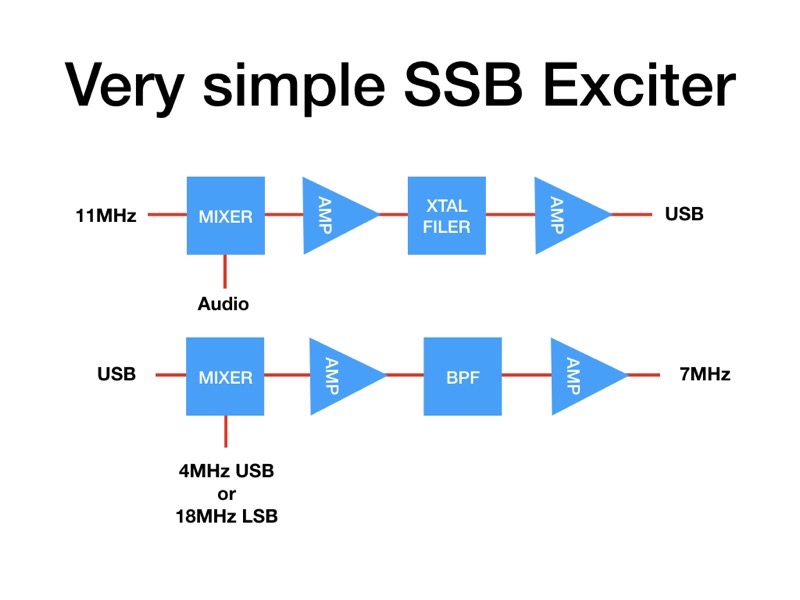
7. How does your blackbox generate SSB? we asked. Turns out few know how it does it (surprising isn't it?). So we designed and built a breadboard to show how it is done. With carrier and VFO RF inputs from our signal generator (#5 above) and audio input from our  audio generator (see #6). The SSB exciter was built using an audio-carrier mixer (11MHz input), followed by a xtal filter (4 stage 11MHz) and another VFO mixer (4 or 18MHz for USB of LSB output) an a final band pass filter and output stage. All stages used BF245 JFET devices.

8. The latest project underway is a GHz VFO digital freuency denerator based on the ADF4351 witha 3.3V Arduino UNO to output around 100MHz to 3GHz. The coding is on-going. (See above blog post)

10. And don't forget our summer "Pixie Challenge". A race to build the low cost RTX kit found on eBay and read a CW beacon transmission in the club house. Followed by a challenge to make a CW QSO with another Pixie. Surprising how rusty our CW was...

That's ZEST. And that's the way to stimulate more club membership and lots more interest in our hobby.

Find out more on this blog and at my download site M0IFA.me


Tuesday, 17 September 2019

WSJT-X my settings

Here are my setting for WSJT-X, I am using an ELAD FDM-DUO SDR TRX and a MacBook or iMac. I hope this may help anyone else trying to set up this excellent program.


Monday, 2 September 2019

New Arduino course

I have written a new course for those wishing to get to grips with Arduino coding and Amateur radio projects.

The two part course can be found on my web site M0IFA.me under CLUB PROJECTS and the sketches are under ALL ARDUINO SKETCHES.

The practical work is done using a kit,  see Kit.


Happy coding.


ADF4351 VFO

This is a new ADF4351 Arduino code for the 4.4GHz synthesiser. It has been developed after taking a look at some other coding published on the web. But with the objective of making a library header file with some simple functions.


- init() - initialise the device and communications
- setFreq(freq, channel) - calculate the ADF4351 register values
- update() - update the device registers

There are also simple functions to set the power output and enable/disable to output. Full details of the Arduino code and a description of how the code works is at M0IFA.me. Here's a block diagram of the ADF4351 with the register names (e.g register2, position 25 on 32bit word). You can see the complexity of programming to get everything right in these 6 x 32 bit registers.


There are essentially three parts to the diagram. Generating Fpfd from the RFin (the xtal 10MHz). Dividing down the RFout to feed the phase comparator, and the phase comparator and VCO. All this is explained is a tech article on my web site here.

The module is from eBay ADF4351 module

And the Arduino is from eBay also Funduino


Friday, 15 March 2019

New download site M0IFA.me

Try my new download site

M0IFA.me


The organisation is in the readme.txt file. Feel free to download and reuse any of the content. Some libraries are covered by licences.

Thursday, 14 March 2019

SSB Exciter Hardware

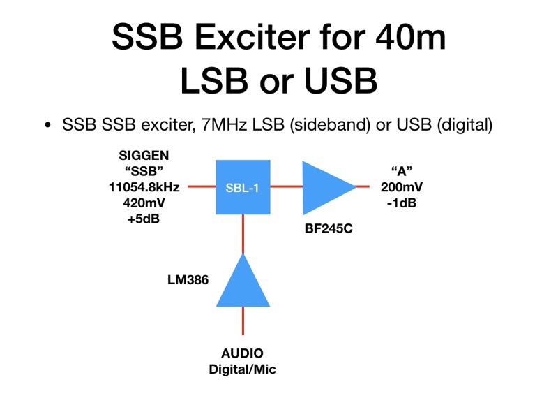
This is the hardware design, so far, for the minimal SSB exciter. It has been made as simple as possible, and does not give a super performance. It was developed to illustrate the principle of SSB generation.

SSB Exciter 001 SSB Exciter 002 SSB Exciter 003 SSB Exciter 004 SSB Exciter 005 SSB Exciter 006 SSB Exciter 007 SSB Exciter 008 SSB Exciter 009 SSB Exciter 010

Sunday, 3 March 2019

The FT8 world's gone mad

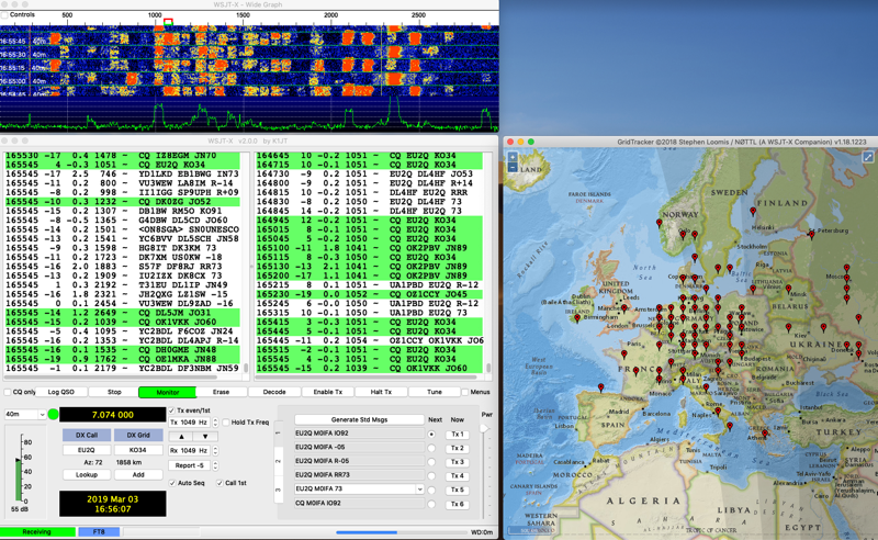
It's Sunday, the day when all radio amateurs find the chance to get in their shacks. And wow are they hitting the airwaves today, with FT8's 3kHz bandwidth around 7074kHz jam packed full. Look:

Screenshot 2019 03 03 at 16 56 07

This is the signals from my tiny loop antenna fed directly to my Elektor Arduino/SDR.

If you're a MacOS man...

Windows is not the dominant OS these days, many are using Linux and many more MacOS on Apple computers. But the world of Amateur radio is poorly served by manufacturers, especially SDR transceiver people, for the Mac. So here's what I have found so far

I am using the windows emulator Crossover (basically a graphic front end to the open source "Wine" system.

MACOS native apps

1. MultiMode Cocoa - just about every digital mode supported, PSK31, SSTV etc

2. cocoaModem - another app supporting digital modes, including here Hellscriber

3. MultiScan - for SSTV

4. fldigi - well known digi-mode app

5. SDR Radio - a rather poor SDR program, great, simple interface but poor config and audio management

6. gqrx - works well for rTL sticks

7. cubicSDR - the out and out winner SDR program. But a bit "industrial", not a friendly interface

8. WSJT-X - the must have FT8 app

9. GridTracker - nice visual of stations on a map, has useless features

10. JT-BRIDGE - pretty, display of stations, country, distance away, etc, but for what?

11. JSCAll - the new "FT8-like" full message app. Does not fully work as a Mac app, and the interface is poor

WINDOWS - if you must

I just moved from using Crossover (a kinda Wine GUI) to running Parallels and installing Windows 10. This all works smoothly but gobbles up RAM. Better to have 32GB if you can, just about works on my MacBook with 8GB. USB and Audio interfaces are problematic, but with enough digging into the terrible old fashioned Windows control panels they can be got to work, I think - it's early days. Anyway I have HDSDR running at 96kHz input (+/-48kHz displayed). I am checking to make sure ELADs FDM-SW2 will run OK under Windows, as I am thinking of buying an FDM-DUO SDR transceiver. A very modern SDR design.

Thursday, 28 February 2019

JS8 Call

Largely based on the well known WSTJ-X, FT8 software, there is a new one called JS8CALL. FT8 sends brief 13 character messages in 15 second slots. JS8 extends this to send longer messages in one or more slots. Thus allowing a two way open chat. FT8 for 40m is based at 7074kHz USB, JS8 is higher at 7078kHz USB. This is so far what I have received:

Screenshot 2019 02 28 at 17 08 59

Showing the FT8 mass of signals at 7074kHZ and a single solitary JS8 signal just above 7078kH - as received on the Hack Green web SDR. And this is a decode of signals received on my Elektor SDR receiver:

Screenshot 2019 02 28 at 16 26 22

Thursday, 21 February 2019

SSB Exciter project - Arduino sketch

Of course the other challenge of the SSB Exciter project is writing the Arduino sketch to control the three outputs of the Si5351 synthesiser. The sketch will run on an Arduino Nano with limited program memory, so can't be too fanciful and must be optimised throughout.

It needs to generate three outputs. CLK0 will be a 7.0-7.2MHz frequency for the VFO of the DCRX Direct Conversion Receiver. CLK1 will be the 11MHz input to the first SSB mixer (11054.8kHz for USB generation. CLK2 must be the mixing frequency to get the USB & LSB 11MHz signals to a final 7.0-7.2MHz for the 40m band. This is done by outputting SSB - freq for USB and a SSB + freq for LSB.

The code runs on the SIGGEN hardware designed during the BARSicle project (see many previous postings), an Arduino Nano drives an OLED display and a three output Si5351 synthesiser module, controlled by a rotary encoder with push switch.

The rotary encoder will tune in 10kHz to 10Hz steps, chosen by a short push on the encoder switch. A long 'hold' on the switch will change from USB to LSB and back. The OLED display will be simple, showing the tuned frequency (in kHz 7000.00 to 7200.00)), the sideband (USB or LSB) and the tuning step (10H to 10kHz). The previously written "Oled.h" header file using the u8g2 library will format these displays.

Here's the initial code, not yet available for download but can be cut and pasted from here, The libraries are part of previous downloads available (look below)

// SSB_EXCITER
// CLK0 = RX, CLK1 = SSB (11MHz), CLK2 = VFO (4 | 18MHz)

#include "Oled.h"                                         // include header
#include "si5351.h"                                       // include library
#include "Rotary.h"                                       // include library

#define CLK 3                                             // encoder connnections
#define DT 2                                              // reverse 2&3 if wrong direction
#define SW 4
#define HOLD 500                                          // held button time > 0.5sec

#define CALIBRATION -150000                               // frequency CALIBRATION

#define SSB 1105480000                                    // SSB USB freq

Si5351 dds;                                               // create dds object
Rotary enc = Rotary(CLK, DT);                             // create enc object

uint64_t freq = 700000000;                                // first init freq (cHz), 7MHz
uint64_t freqStep = 100000;                               // init step (cHz), 1kHz

bool sideband = true;                                     // start on USB

void setup() {
  pinMode(CLK, INPUT_PULLUP);                             // encoder inputs, with pull-ups
  pinMode(DT, INPUT_PULLUP);
  pinMode(SW, INPUT_PULLUP);

  oled.begin();                                           // begin OLED

  dds.init(SI5351_CRYSTAL_LOAD_8PF, 0, CALIBRATION);      // set xtal capacitance, 25MHz, & CALIBRATION

  dds.drive_strength(SI5351_CLK0, SI5351_DRIVE_8MA);      // output drive (~+10dBm)
  dds.drive_strength(SI5351_CLK1, SI5351_DRIVE_8MA);      // output drive (~+10dBm)
  dds.drive_strength(SI5351_CLK2, SI5351_DRIVE_8MA);      // output drive (~+10dBm)

  dds.output_enable(SI5351_CLK0, 1);                      // enable
  dds.output_enable(SI5351_CLK1, 1);                      // enable
  dds.output_enable(SI5351_CLK2, 1);                      // enable

  freqOut(freq);                                          // output initial frequencies

  dispUpdate();                                           // display
}

void loop() {
  long hold;                                              // button hold time
  unsigned char result;                                   // encoder result

  if (digitalRead(SW) == LOW) {                           // enc button push
    hold = millis();                                      // start hold count
    while (!digitalRead(SW));                             // wait release
    if (millis() - hold > HOLD) {                         // button hold > HOLD time, change sideband
      sideband = !sideband;
      freqOut(freq);                                      // update frequencies
      dispUpdate();
    }
    else if (freqStep == 1000) freqStep = 1000000;        // update step if 10Hz -> 10kHz
    else freqStep = freqStep / 10;                        // step down
    dispUpdate();                                         // display
  }

  result = enc.process();                                 // read encoder
  if (result == DIR_CW) {                                 // freq up
    freq += freqStep;
    freqOut(freq);
    dispUpdate();
  }
  if (result == DIR_CCW) {                                // freq down
    freq -= freqStep;
    freqOut(freq);
    dispUpdate();
  }
}

// CLK0 = RX, CLK1 = SSB (11MHz), CLK2 = VFO (4 | 18MHz)
void freqOut(uint64_t freq) {
  dds.set_freq(freq, SI5351_CLK0);                         // RX freq 7MHz
  dds.set_freq(SSB, SI5351_CLK1);                          // SSB freq 

  if (sideband) {
    dds.set_freq(SSB - freq, SI5351_CLK2);                 // VFO USB freq
  }
  else {

    dds.set_freq(SSB + freq, SI5351_CLK2);                 // VFO LSB freq
  }
}

void dispUpdate() {                                        // picture loop
  oled.firstPage();
  do {
    dispMsg(35, 0, "SSB TCVR");                                 // display title
    dispFreq(15, 20, freq / 100, 0, 2);                    // display frequency, in kHz
    if (sideband)
      dispMsg(10, 50, "USB");
    else
      dispMsg(10, 50, "LSB");
    dispStep(80, 50, freqStep / 100);                      // display step freq
  } while ( oled.nextPage() );
}

Monday, 18 February 2019

SSB Exciter project - XTAL FILTER

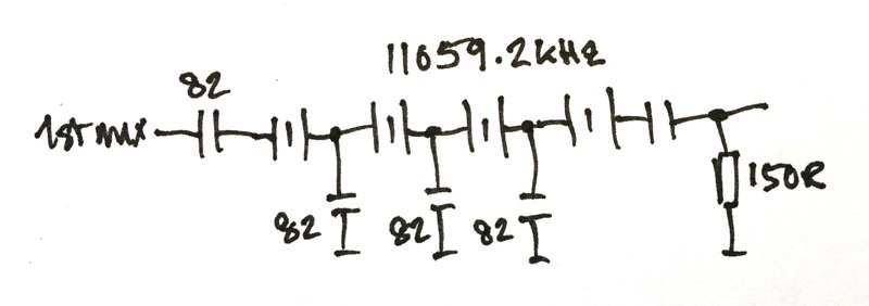
So the next step is to try out a Xtal filter. I have four 11059.2kHz xtals and have wired them up like this

IMG 0082

I tried them out on the breadboard, which is not the best place to build a xtal filter! I connected the input directly to the Si5351 SIGGEN output and measured the response using my RF Meter. The breadboard now looks like this

IMG 0970

This is what I got

Screenshot 2019 02 18 at 16 15 28

The filter is 2.9kHz wide. And to generate USB the carrier should be at 11056.2kHz, and for LSB 11059.1kHz. All is looking good. The circuit now needs an output buffer. When I have built this I will have basically the first half of my exciter done.

SSB exciter project - 1st MIXER

One of the projects I want to get "under my belt" is an SSB exciter. It has always seemed to me to be a black art or magic to generate SSB signals. I mean I know on paper how its done, but to build a system...? That's another matter. Anyway I have started, this is the plan

Screenshot 2019 02 18 at 13 18 05

The first mixer will generate DSB signals at 11MHz, this will be sent to a xtal filter with a bandwidth of 2.5-3kHz, this sill then go to a 2nd mixer with inputs at 4 or 18MHz to be mixed down to 7MHz LSB or USB, finally there will an output amp to give at least +10dBm output.

The mixers will be the commercial SBL-1 double balanced mixers which have an excellent performance.

1ST MIXER

Here's my schematic for the 1st mixer

1st MIXER sch

The RF input is at a relatively high level to switch the internal mixer diodes, it comes straight from the "0" output of a Si5351 frequency synthesiser. The audio input is via a 51R "load" resistor, it currently comes from my Audio Synthesiser (see previous posting) which has an LM386 output amplifier. The level is 200-300mVrms. The RF output is across the 20uH choke (10t/FT37-43) loaded by a 150R resistor - which will be the input impedance for the xtal filter.

Here's the breadboard

1st MIXER bb

OUTPUT

These are two shots of the output. I used a simple Elektor SDR receiver, via a 40dB attenuator and into my MacBook running the Cubic SDR program.

Screenshot 2019 02 18 at 13 44 40

Screenshot 2019 02 18 at 13 44 25

I am running it at 11MHz. As you can see the output is the two sidebands 1kHz away from the centre frequency.

Monday, 11 February 2019

Finished Audio SIGGEN

I have boxed up the Audio SIGGEN. This provides an output of up to +10dBV, 3.2V rms and can drive a low impedance load. The frequency range is from 10Hz up to 100kHz in steps of 10, 100, 1KHz and 10kHz. It operates from a 12V supply.

Inside the box are an Arduino UNO, an AD9833 digital frequency synthesiser with analog output (scanned ROM) and an LM386 audio amplifier.

IMG 0885

Operating with my home built 12V power linear supply

IMG 0884

Thursday, 31 January 2019

Update on Digital Audio Siggen

I have made what I hope will be the last update to the Digital Audio Siggen. This is to use an LM386 as the output amplifier. I bought an amazing kit for £1.56 on eBay, a complete amplifier with gain control!!! So the schematic is now this:

ASG sch

If I decide to build this, I may do a PCB. This is the hard wired prototype.

IMG 0883

The output is up to a little above 10dBV up to 100kHz - pretty good for the LM386!

UPDATE

Later I found that 12V was too much for the LM386 I had an it blew up - seems you need a special version fo ruse at 12V and above. So I have removed the amplifier for now.

Code update here

Sunday, 6 January 2019

Sythesised Audio Oscillator

While many struggle to build audio signal generators using phase shift networks, voltage and gain stabilisers and bunches of op-amps, there is another solution. Digital synthesis.

AD9833

The AD9833 is an IC designed for generating Sine, Triangle or Square waves from 0Hz up to +10MHz. It is simple to use with an Arduino to build a variable frequency sine wave generator. Combined with a Rotary Encoder and an OLED display an accurate audio generator can be made for about 20€!

Here's the circuit.

IMG 0835
And here's the mockup

IMG 0834

Code here.