So the next step is to try out a Xtal filter. I have four 11059.2kHz xtals and have wired them up like this
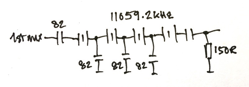
I tried them out on the breadboard, which is not the best place to build a xtal filter! I connected the input directly to the Si5351 SIGGEN output and measured the response using my RF Meter. The breadboard now looks like this

This is what I got

The filter is 2.9kHz wide. And to generate USB the carrier should be at 11056.2kHz, and for LSB 11059.1kHz. All is looking good. The circuit now needs an output buffer. When I have built this I will have basically the first half of my exciter done.
Monday, 18 February 2019
SSB Exciter project - XTAL FILTER

SSB exciter project - 1st MIXER
One of the projects I want to get "under my belt" is an SSB exciter. It has always seemed to me to be a black art or magic to generate SSB signals. I mean I know on paper how its done, but to build a system...? That's another matter. Anyway I have started, this is the plan

The first mixer will generate DSB signals at 11MHz, this will be sent to a xtal filter with a bandwidth of 2.5-3kHz, this sill then go to a 2nd mixer with inputs at 4 or 18MHz to be mixed down to 7MHz LSB or USB, finally there will an output amp to give at least +10dBm output.
The mixers will be the commercial SBL-1 double balanced mixers which have an excellent performance.
1ST MIXER
Here's my schematic for the 1st mixer

The RF input is at a relatively high level to switch the internal mixer diodes, it comes straight from the "0" output of a Si5351 frequency synthesiser. The audio input is via a 51R "load" resistor, it currently comes from my Audio Synthesiser (see previous posting) which has an LM386 output amplifier. The level is 200-300mVrms. The RF output is across the 20uH choke (10t/FT37-43) loaded by a 150R resistor - which will be the input impedance for the xtal filter.
Here's the breadboard

OUTPUT
These are two shots of the output. I used a simple Elektor SDR receiver, via a 40dB attenuator and into my MacBook running the Cubic SDR program.


I am running it at 11MHz. As you can see the output is the two sidebands 1kHz away from the centre frequency.
Monday, 11 February 2019
Finished Audio SIGGEN
I have boxed up the Audio SIGGEN. This provides an output of up to +10dBV, 3.2V rms and can drive a low impedance load. The frequency range is from 10Hz up to 100kHz in steps of 10, 100, 1KHz and 10kHz. It operates from a 12V supply.
Inside the box are an Arduino UNO, an AD9833 digital frequency synthesiser with analog output (scanned ROM) and an LM386 audio amplifier.

Operating with my home built 12V power linear supply
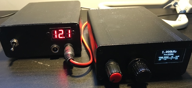
Inside the box are an Arduino UNO, an AD9833 digital frequency synthesiser with analog output (scanned ROM) and an LM386 audio amplifier.
Operating with my home built 12V power linear supply
Thursday, 31 January 2019
Update on Digital Audio Siggen
I have made what I hope will be the last update to the Digital Audio Siggen. This is to use an LM386 as the output amplifier. I bought an amazing kit for £1.56 on eBay, a complete amplifier with gain control!!! So the schematic is now this:

If I decide to build this, I may do a PCB. This is the hard wired prototype.

The output is up to a little above 10dBV up to 100kHz - pretty good for the LM386!
UPDATE
Later I found that 12V was too much for the LM386 I had an it blew up - seems you need a special version fo ruse at 12V and above. So I have removed the amplifier for now.
Code update here
If I decide to build this, I may do a PCB. This is the hard wired prototype.
The output is up to a little above 10dBV up to 100kHz - pretty good for the LM386!
UPDATE
Later I found that 12V was too much for the LM386 I had an it blew up - seems you need a special version fo ruse at 12V and above. So I have removed the amplifier for now.
Code update here
Sunday, 6 January 2019
Sythesised Audio Oscillator
While many struggle to build audio signal generators using phase shift networks, voltage and gain stabilisers and bunches of op-amps, there is another solution. Digital synthesis.
AD9833
The AD9833 is an IC designed for generating Sine, Triangle or Square waves from 0Hz up to +10MHz. It is simple to use with an Arduino to build a variable frequency sine wave generator. Combined with a Rotary Encoder and an OLED display an accurate audio generator can be made for about 20€!
Here's the circuit.

And here's the mockup
Code here.

Thursday, 27 December 2018
First FT8 QSO!!!
I finally moved my operating position from the hall downstairs where I didn't receive any FT8 signals better than -15 or so. Now I am upstairs and signals are coming in 0 to -10. So I clicked on the huge signal coming in at 0 to -8, and low and behold he received me and I got my first FT8 QSO!
Here it is

I am using the fixed frequency QRPver transceiver with their 6W PA amplifier into a WonderWand loop on the window sill, I have it in line with my home designed and made VSWR meter (see previous postings) and I get an SWR of 1:1.50. Anyway this is very encouraging.
Note
When I received my transceiver from QRPver it was tuned to JT65 7076kHz, I delved inside and tuned it down to 7074kHz and it has settled about +50Hz high right now but quite functional. Nice little unit. Audio I/O is via a very cheap Amazon USB sound dongle to my MacBook.
The other thing I have done is to use a 40dB attenuator in the audio output line as otherwise it overloads the USB Dongle microphone input. The QRPver audio works at line levels, which is OK for the headphone output to the TX input, but too much for RX output to the microphone input.


Very pleased with myself.
Sunday, 16 December 2018
Aerial plans
For years I have been stuck with without aerial, I have a small loop and a pull up whip both tuned, but they are very inefficient... What's worse is that my house is old, and insulated on the outside - layer of aluminium and then polystyrene blocks! So I am living in a Faraday Cage. Seems stupid. but he facts are that where I living no outside aerials are permitted, and I do not have a way to run a cable from my loft to my operating position in the downstairs hall.
But now, we are going to re-arrange the house, which will mean an upstairs bedroom will be my new location, a simple drop down from the loft above. So a loft antenna it is.
First I need a balun as it will be a sort of tuned dipole as much as I can get into the space. The target frequency is the 40m band. So here it is

A conventional design built in a small plastic box. Looks good. Two terminals and a PL259 connector.
The antenna was put up by my son in our attic. When I checked it out - using my trusty Si5351 SIGGEN and a resistor bridge feeding my trusty RF POWER METER. I found it was resonant at 8.3MHz, too high. So far I have not persuaded my son to come back and lengthen the two sides, by stretching out the spring thingy.
But now, we are going to re-arrange the house, which will mean an upstairs bedroom will be my new location, a simple drop down from the loft above. So a loft antenna it is.
First I need a balun as it will be a sort of tuned dipole as much as I can get into the space. The target frequency is the 40m band. So here it is
A conventional design built in a small plastic box. Looks good. Two terminals and a PL259 connector.
The antenna was put up by my son in our attic. When I checked it out - using my trusty Si5351 SIGGEN and a resistor bridge feeding my trusty RF POWER METER. I found it was resonant at 8.3MHz, too high. So far I have not persuaded my son to come back and lengthen the two sides, by stretching out the spring thingy.
Subscribe to:
Posts (Atom)