Thursday 28 November 2013

Bluetooth communications for the Arduino

I have never seen such confusing garbage on various web sites as when I searched for Bluetooth use on the Arduino.

I found there are two modules common on the market, the HC-05 and HC-06. There is also a JY-MCU with two versions for "slave" only or "master - slave" applications.

The JY-MCU provides only a "slave" connection if you buy the one that uses the HC-06 module. This is the one described here.

These are the connections for a simple system:

Screen Shot 2013 11 28 at 16 45 54

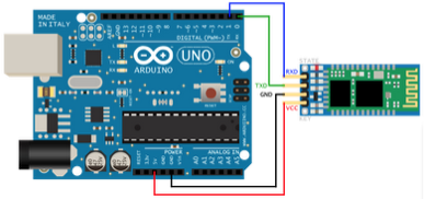
Take care the Bluetooth BTX goes to the Arduino ARX (0) and BRX to ATX (1).

The Bluetooth name of this module is set by some AT commands you give. The password or PIN for pairing is changed to 0000. The default baud rate is 9600bps.

Two ways to program

If the module is simply connected as above to the Arduino serial RX & TX pins (0 and 1), which are also used by the USB connection, then the Serial.h library can be used. Like this:

#include "Serial.h"

#define LEDPIN 8

void setup() {

  pinMode(LEDPIN, OUTPUT);
  
  Serial.begin(9600); // start serial comms on default pins 0 & 1
}

void loop() {

  char v;

  if(Serial.available() > 0) // if data in the serial buffer, read it
    v = Serial.read();

  if(v == ‘H’) {
    digitalWrite(LEDPIN, HIGH); // turn LED on
  {
  else if(v == ‘L’) {
    digitalWrite(LEDPIN, LOW); // turn LED off
  }

  delay(100);
}


These steps must be followed as the USB must be inactive when the BT is connected as they use the same signals on pins 0 & 1.

1 Connect USB to power BT module, only +5 and GND connected

2 Pair MAC to BT module

3 Run this simple sketch to find the BT device port

void setup() {

    Serial.begin);
    println(Serial.list());
  }


4 Load the BT sketch above via USB and then go to IDE > Tool > Serial Port and click on the device for the BT module

5 Disconnect USB, wire up the BT module RX and TX signals, connect battery supply

6 Reset Arduino to run the BT sketch above

7 Open IDE Serial Monitor which should now be talking to the BT

8 Enter H or L to control LED via Bluetooth

To stop using BT remove the connections to pin 0 RX and pin 1 TX and chose the IDE Serial Port device for USB.

Arduino SoftwareSerial library

The second way is by using the SoftwareSerial.h library, using any other pins, but not RX 0 & TX 1.

You find the BT device port as in 3 above to be able to connect in the IDE.

#include "SoftwareSerial.h"

// BT TX to pin 10 ARX, RX to pin 11 ATX
#define ARX 10
#define ATX 11

SoftwareSerial myBT(ARX, ATX); // create BT object

// can use both USB and BT ports
void setup() {

  Serial.begin(9600); // open comms via USB device port, chose in IDE
  myBT.begin(9600); // open comms via BT device port, chose in IDE 

}

void loop() {

  if(myBT.available()) {

   // do something, e.g. char x = myBT.read();
  }


  if(Serial.available()) {
    // do something e.g. char x = Serial.read();
  }
}


Nothing here has yet been tested as I have not yet received my BT module, but when it arrives I will try it out and update this post.

Monday 25 November 2013

Send morse messages from KB

There is an Arduino library called MorseEnDecoder.h which can be used for encoding characters and send them as morse code at a fixed WPM. It can also be used for decoding received morse (but at a fixed WPM...).

The output of the program is a TTL signal an Arduino pin. This must be used to drive an external oscillator if audio is required, it can drive a relay directly to key a transmitter if no local audio is required - or it could do both!

The oscillator circuit uses a TTL 74LS00:

2013 11 25 17 56 33

Here's the code:

// sends TTL signal on OSCPIN to a TTL external osillator
// input from Serial Monitor, "string_to_send CR"

#include "avr/pgmspace.h"
#include "MorseEnDecoder.h"

#define WPM 5

#define OSCPIN 7

// morseOut class
morseEncoder morseOut(OSCPIN);

// timing
long lastTrans;
long current;
boolean ended = true;

void setup() {
  
  pinMode(OSCPIN, OUTPUT);
  
  Serial.begin(9600);
  
  morseOut.setspeed(WPM);
  
  lastTrans = millis();
}

void loop() {
  
  current = millis();
  
  morseOut.encode(); // must call once per loop
  
  if(Serial.available() && morseOut.available()) {
    char letter = Serial.read(); // read the next letter
    morseOut.write(letter); // send the letter
  }
  
  if(!morseOut.available()) {
    lastTrans = current;
    ended = false;
  }
}

Send morse code with an Arduino

Here is a very simple morse code sender, with at the moment hard wired text words to send. I hope to develop this to accept keyboard input and send it...

The circuit is very simple, a Piezo transducer is connected to pin 2, a LED to pin 7 and a push button to pin 8. Pushing the button sends the text "CQ CD DE M6KWH".

2013 11 25 15 25 31

// Morse sender

// pins
#define PIEZOPIN 2
#define BUTTONPIN 8
#define LEDPIN 7

// text array codes
#define DOT 0
#define DASH 1
#define SPACE 2
#define WORD 3

// text words
int CQ[] = {1,0,1,0,2,1,1,0,1,3};
int DE[] = {1,0,0,2,0,3};
int M6KWH[] = {1,1,2,0,1,1,1,1,2,1,0,1,2,1,1,0,2,0,0,0,0,3};

// sound frequency 1000Hz
// cycle time = 1000000/frequency(Hz) usec
#define CYCLE 1000

// dash = 3 dots, space = 3 dots, word = 7 dots
#define DOTTIME 150

void setup() {

  pinMode(BUTTONPIN, INPUT);
  pinMode(PIEZOPIN, OUTPUT);
  pinMode(LEDPIN, OUTPUT);
}

void loop() {

// wait for button pressed 
  while(digitalRead(BUTTONPIN) != LOW);

// send message words
  sender(CQ);
  sender(CQ);
  sender(DE);
  sender(M6KWH);

// finger still on button?
  while(digitalRead(BUTTONPIN) != HIGH);
  delay(100); // avoid button bounce
}

// send a word
void sender(int dida[]) {

  int x = 0; // array index

// send characters up to end of word
  while(dida[x] != WORD) {
   switch (dida[x]) {
    case DOT:
       sound(DOTTIME);
       delay(DOTTIME); // add after dot
       break;
    case DASH:
        sound(3 * DOTTIME);
        delay(DOTTIME); // add after dash
        break;
    case SPACE:
         delay(2 * DOTTIME);  // add for space
         break;
    }
    x++;
  }
  delay(6 * DOTTIME); // add   for word
}

// make sound at FREQ for time (msec)
void sound(long time) {

  long start;

// make the sound for time msec
  start = millis(); // read current time
  digitalWrite(LEDPIN, HIGH); // turn on LED

// loop until time has passed making sound
  while(millis() < start + time) {
    digitalWrite(PIEZOPIN, HIGH);
    delayMicroseconds(CYCLE/2);
    digitalWrite(PIEZOPIN, LOW);
    delayMicroseconds(CYCLE/2);
  }
  digitalWrite(LEDPIN, LOW); // turn off LED
}

Monday 18 November 2013

Update on One Wheel Robot

I have made soms updates to both the hardware and the code, so here they are.

Hardware wiring:

2013 11 18 10 26 12 
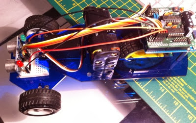
There are now four I/Os, the steering servo, a light detector under the from of the robot, two LEDs (red and green) which show the steering direction and the sonar detector for obstacle detection.

The latest code is:

// This is my second go at the one wheel robot. Sigificant program parts are: 
// 1 lots of defines to set parameters, hope to make the code easier to understand later
// 2 LED show the chosen steering direction, for no particular reason other than pretty
// 3 servo angles set it to centre, and R or L
// 4 when a random direction is chosen for forward or reverse, it is biased to the centre
// differently for fwd or rev. bigger number = more bias towards chosing centre direction
// 5 velocity is set, but in reverse it is reduced
// 6 the robot goes forward for a time, then choses a random direction, so as to "roam" around
// 7 if the sonar detects a crash then it backs out either R or L but not C
// 8 a couple of settle times are used to stabilise the operation against hardware glitches
// 9 if it comes across a white place then it stops (parking place!), waits for 10sec then gos off straight

#include "Servo.h"
#include "NewPing.h"

// piezo pin
#define PIEZOPIN A3

// LED pins
#define GREENPIN 2
#define REDPIN 1

// light detector pin
#define LIGHTPIN A4
#define DARK 500

// sonar pins & max distance (above this returns 0)
#define TRIGPIN 5
#define ECHOPIN 4
#define MAXDIST 100

// RobotShield driver pins for motor A
#define MOTORADIRPIN 8
#define MOTORASPEEDPIN 6

// servo pin
#define SERVOPIN A5

// steering positions
#define STEERCENTRE 85
#define STEERLEFT 115
#define STEERRIGHT 55

// random direction bias towards straight(0), 1-3 = left(1), 4-7 = right(2)
#define BIAS 15
#define REVBIAS 10
#define CENTRE 0
#define LEFT 1
#define RIGHT 2

// crash detect distance (cm)
#define CRASH 15

// drive speeds (0 - 255) and directions
#define FWDSPEED 130
#define REVSPEED 130
#define STOP 0
#define FWD 1
#define REV 2

// various timings (msec)
#define FWDTIME 500
#define REVTIME 2000
#define SETTLE 50
#define PARKTIME 10000

Servo steering;  // create servo object
NewPing sonar(TRIGPIN, ECHOPIN, 100); // create NewPing object, max 100 cm away

unsigned long ms, pms;

// =================SETUP================
void setup() {

  // define I/Os
  
  pinMode(GREENPIN, OUTPUT); // LED pins
  pinMode(REDPIN, OUTPUT);
  
  pinMode(LIGHTPIN, INPUT);
  
  pinMode(TRIGPIN, OUTPUT); // sonar pins
  pinMode(ECHOPIN, INPUT);
  
  pinMode(MOTORADIRPIN, OUTPUT); // motor pins for direction and speed
  pinMode(MOTORASPEEDPIN, OUTPUT);
  
  pinMode(SERVOPIN, OUTPUT); // servo pin
  
  // connect servo
  
  steering.attach(SERVOPIN);
  
  // seed random generator
  
  randomSeed(analogRead(A0));
}
  
// =================LOOP================
void loop() {
  
  // wander about
    
  long cm;
  unsigned int dir;
  
  // if find white parking place then stop
  
  if(analogRead(LIGHTPIN) < DARK) {
    drive(STOP, STOP);
    delay(PARKTIME);
    steering.write(STEERCENTRE); // go off straight
    while(analogRead(LIGHTPIN) < DARK) {  // go until off white area
     drive(FWD, FWDSPEED);
    }
  }  
  
  // check for obstacles, if none go forward
  

  cm = sonar.ping_cm(); // get distance (cm), convert us to cm, 60us/cm is roundtrip speed of sound
  delay(50); // at least 50usec between sonar pings
  
  if(cm  == 0 || cm > CRASH) { // no obstacle in CRASH distance out to MAXDIST (returns 0)
  
    drive(FWD, FWDSPEED); // go forward
    
    ms = millis(); // change direction if more than FWDTIME has passed
    if(ms > pms + FWDTIME) {
      dir = randir(BIAS); // save direction chosen, based on BIAS, for use in choice of reverse direction below
      pms = ms;
    }

  }
  
  // obstacle found, reverse away
  
  else {
    
    if(dir == LEFT) steering.write(STEERRIGHT); // if dir was L then R
    else if(dir == RIGHT) steering.write(STEERLEFT); // if dir was R then L
    else while(randir(BIAS) == CENTRE); // if was centre set to only L or R
    drive(REV, REVSPEED);
    delay(REVTIME); // for a time
  }
  
  // loop stabilisation settle time
  
  delay(SETTLE);

}

// chose a random direction, returns direction chosen, lights LEDs
int randir(int limit) {
  
              int x, result;
        
              digitalWrite(REDPIN, LOW); // LEDs off
              digitalWrite(GREENPIN, LOW);
              
              x = random(1, limit); // random direction
              if(x < 4) {
                  steering.write(STEERLEFT);
                  digitalWrite(REDPIN, HIGH); // red LED on
                  result = LEFT;
              }        
              else if(x > 3 && x < 7) {
                  steering.write(STEERRIGHT);
                  digitalWrite(GREENPIN, HIGH); // green LED on
                  result = RIGHT;
              }
              else {
                steering.write(STEERCENTRE);
                result = CENTRE;
              }
              
              delay(SETTLE);
              return result;
}

// drive forward at vel 0-255, cmd = 0 STOP, cmd = 1 FWD, cmd = 2 REV
void drive(int cmd, int vel) {
  
    switch (cmd) {
      case 0: // stop
        analogWrite(MOTORASPEEDPIN, STOP);
        break;
      case 1: // fwd
        digitalWrite(MOTORADIRPIN, HIGH);
        break;
       case 2: // rev
        digitalWrite(MOTORADIRPIN, LOW);
        break;
    }
    analogWrite(MOTORASPEEDPIN, vel);  // set speed
}  
I have the thought to put in some sound generation, maybe the pip, pip, pip when reversing. This would be done by connecting a piezo transducer to A3 output and using the "pitches.h" library and tone() function.

Wednesday 13 November 2013

Been quiet around here, for a good reason

I have just immersed myself in the microcomputer called the Arduino. This is a very flexible single board computer with an excellent program development system running on my Mac.

The Arduino has lots of input/outputs, six of which can be used as analog inputs for measuring voltages of 0-5V. All I/Os can be used for digital input or output. Six of the digital outputs can output PWM signals to emulate an analog output. This is the board:

Screen Shot 2013 11 13 at 16 21 03

Along side this I have purchased a "Starter Kit", looks like this:

Kit box

Inside is everything you need, and more, to do a series of practical experiments, complete with a book giving full and simple instructions.

Inside box

Anyone could grasp microcomputer programming with this kit. But to help Arduino has an excellent web site at arduino.cc.

My robot

After I had done all the exercises and learnt how to program, I then purchased a one wheel robot chassis and a RobotMotor driver board which plugs on top of the Arduino. I wired this up to the drive motor, steering servo, an ultrasonic range detector and a couple of LEDs which show the steering direction. The robot looks like this:

One Wheel Robot

Programming

Now comes the tough bit! Writing a program to make the robot do something. A simple robot like this with only one sensor, for range, capable of measuring from about 2 - 200 cm. Based on this input I wanted the robot to roam around the room, and avoid crashing by backing up when it got closer than 20 cm to anything. It should roam around in a random pattern and back up in a sensible way.

The latest code is in the post above.