Largely based on the well known WSTJ-X, FT8 software, there is a new one called JS8CALL. FT8 sends brief 13 character messages in 15 second slots. JS8 extends this to send longer messages in one or more slots. Thus allowing a two way open chat. FT8 for 40m is based at 7074kHz USB, JS8 is higher at 7078kHz USB. This is so far what I have received:

Showing the FT8 mass of signals at 7074kHZ and a single solitary JS8 signal just above 7078kH - as received on the Hack Green web SDR. And this is a decode of signals received on my Elektor SDR receiver:

Thursday 28 February 2019
JS8 Call
Thursday 21 February 2019
SSB Exciter project - Arduino sketch
Of course the other challenge of the SSB Exciter project is writing the Arduino sketch to control the three outputs of the Si5351 synthesiser. The sketch will run on an Arduino Nano with limited program memory, so can't be too fanciful and must be optimised throughout.
It needs to generate three outputs. CLK0 will be a 7.0-7.2MHz frequency for the VFO of the DCRX Direct Conversion Receiver. CLK1 will be the 11MHz input to the first SSB mixer (11054.8kHz for USB generation. CLK2 must be the mixing frequency to get the USB & LSB 11MHz signals to a final 7.0-7.2MHz for the 40m band. This is done by outputting SSB - freq for USB and a SSB + freq for LSB.
The code runs on the SIGGEN hardware designed during the BARSicle project (see many previous postings), an Arduino Nano drives an OLED display and a three output Si5351 synthesiser module, controlled by a rotary encoder with push switch.
The rotary encoder will tune in 10kHz to 10Hz steps, chosen by a short push on the encoder switch. A long 'hold' on the switch will change from USB to LSB and back. The OLED display will be simple, showing the tuned frequency (in kHz 7000.00 to 7200.00)), the sideband (USB or LSB) and the tuning step (10H to 10kHz). The previously written "Oled.h" header file using the u8g2 library will format these displays.
Here's the initial code, not yet available for download but can be cut and pasted from here, The libraries are part of previous downloads available (look below)
// SSB_EXCITER
// CLK0 = RX, CLK1 = SSB (11MHz), CLK2 = VFO (4 | 18MHz)

#include "Oled.h"                                         // include header
#include "si5351.h"                                       // include library
#include "Rotary.h"                                       // include library

#define CLK 3                                             // encoder connnections
#define DT 2                                              // reverse 2&3 if wrong direction
#define SW 4
#define HOLD 500                                          // held button time > 0.5sec

#define CALIBRATION -150000                               // frequency CALIBRATION

#define SSB 1105480000                                    // SSB USB freq

Si5351 dds;                                               // create dds object
Rotary enc = Rotary(CLK, DT);                             // create enc object

uint64_t freq = 700000000;                                // first init freq (cHz), 7MHz
uint64_t freqStep = 100000;                               // init step (cHz), 1kHz

bool sideband = true;                                     // start on USB

void setup() {
  pinMode(CLK, INPUT_PULLUP);                             // encoder inputs, with pull-ups
  pinMode(DT, INPUT_PULLUP);
  pinMode(SW, INPUT_PULLUP);

  oled.begin();                                           // begin OLED

  dds.init(SI5351_CRYSTAL_LOAD_8PF, 0, CALIBRATION);      // set xtal capacitance, 25MHz, & CALIBRATION

  dds.drive_strength(SI5351_CLK0, SI5351_DRIVE_8MA);      // output drive (~+10dBm)
  dds.drive_strength(SI5351_CLK1, SI5351_DRIVE_8MA);      // output drive (~+10dBm)
  dds.drive_strength(SI5351_CLK2, SI5351_DRIVE_8MA);      // output drive (~+10dBm)

  dds.output_enable(SI5351_CLK0, 1);                      // enable
  dds.output_enable(SI5351_CLK1, 1);                      // enable
  dds.output_enable(SI5351_CLK2, 1);                      // enable

  freqOut(freq);                                          // output initial frequencies

  dispUpdate();                                           // display
}

void loop() {
  long hold;                                              // button hold time
  unsigned char result;                                   // encoder result

  if (digitalRead(SW) == LOW) {                           // enc button push
    hold = millis();                                      // start hold count
    while (!digitalRead(SW));                             // wait release
    if (millis() - hold > HOLD) {                         // button hold > HOLD time, change sideband
      sideband = !sideband;
      freqOut(freq);                                      // update frequencies
      dispUpdate();
    }
    else if (freqStep == 1000) freqStep = 1000000;        // update step if 10Hz -> 10kHz
    else freqStep = freqStep / 10;                        // step down
    dispUpdate();                                         // display
  }

  result = enc.process();                                 // read encoder
  if (result == DIR_CW) {                                 // freq up
    freq += freqStep;
    freqOut(freq);
    dispUpdate();
  }
  if (result == DIR_CCW) {                                // freq down
    freq -= freqStep;
    freqOut(freq);
    dispUpdate();
  }
}

// CLK0 = RX, CLK1 = SSB (11MHz), CLK2 = VFO (4 | 18MHz)
void freqOut(uint64_t freq) {
  dds.set_freq(freq, SI5351_CLK0);                         // RX freq 7MHz
  dds.set_freq(SSB, SI5351_CLK1);                          // SSB freq

  if (sideband) {
    dds.set_freq(SSB - freq, SI5351_CLK2);                 // VFO USB freq
  }
  else {

    dds.set_freq(SSB + freq, SI5351_CLK2);                 // VFO LSB freq
  }
}

void dispUpdate() {                                        // picture loop
  oled.firstPage();
  do {
    dispMsg(35, 0, "SSB TCVR");                                 // display title
    dispFreq(15, 20, freq / 100, 0, 2);                    // display frequency, in kHz
    if (sideband)
      dispMsg(10, 50, "USB");
    else
      dispMsg(10, 50, "LSB");
    dispStep(80, 50, freqStep / 100);                      // display step freq
  } while ( oled.nextPage() );
}
Monday 18 February 2019
SSB Exciter project - XTAL FILTER
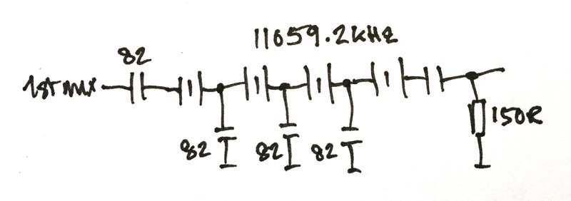
So the next step is to try out a Xtal filter. I have four 11059.2kHz xtals and have wired them up like this
I tried them out on the breadboard, which is not the best place to build a xtal filter! I connected the input directly to the Si5351 SIGGEN output and measured the response using my RF Meter. The breadboard now looks like this
This is what I got

The filter is 2.9kHz wide. And to generate USB the carrier should be at 11056.2kHz, and for LSB 11059.1kHz. All is looking good. The circuit now needs an output buffer. When I have built this I will have basically the first half of my exciter done.
SSB exciter project - 1st MIXER
One of the projects I want to get "under my belt" is an SSB exciter. It has always seemed to me to be a black art or magic to generate SSB signals. I mean I know on paper how its done, but to build a system...? That's another matter. Anyway I have started, this is the plan

The first mixer will generate DSB signals at 11MHz, this will be sent to a xtal filter with a bandwidth of 2.5-3kHz, this sill then go to a 2nd mixer with inputs at 4 or 18MHz to be mixed down to 7MHz LSB or USB, finally there will an output amp to give at least +10dBm output.
The mixers will be the commercial SBL-1 double balanced mixers which have an excellent performance.
1ST MIXER
Here's my schematic for the 1st mixer
The RF input is at a relatively high level to switch the internal mixer diodes, it comes straight from the "0" output of a Si5351 frequency synthesiser. The audio input is via a 51R "load" resistor, it currently comes from my Audio Synthesiser (see previous posting) which has an LM386 output amplifier. The level is 200-300mVrms. The RF output is across the 20uH choke (10t/FT37-43) loaded by a 150R resistor - which will be the input impedance for the xtal filter.
Here's the breadboard
OUTPUT
These are two shots of the output. I used a simple Elektor SDR receiver, via a 40dB attenuator and into my MacBook running the Cubic SDR program.


I am running it at 11MHz. As you can see the output is the two sidebands 1kHz away from the centre frequency.
Monday 11 February 2019
Finished Audio SIGGEN
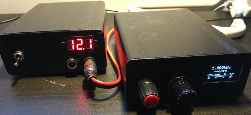
Inside the box are an Arduino UNO, an AD9833 digital frequency synthesiser with analog output (scanned ROM) and an LM386 audio amplifier.

Operating with my home built 12V power linear supply


