Thursday 30 March 2017

BASIC Tech Group - MyNews 34 - More on RTTY, Text input

I have already described a RTTY Beacon that just sends out regular fixed text messages. Here is a modification of that code that allows users to input text messages to be sent out. The Transmit frequency still remains fixed, but that can be updated in the future.

A new Serial Terminal software is used, in place of the one built in to the Arduino IDE (I have so often opened a sketch , opened the Serial Monitor, then accidentally typed text into the sketch not the monitor window! that I decided to use a dedicated Serial Terminal program, its called iSerialTerm (Mac only)).

Screen Shot 2017 03 30 at 11 30 43 
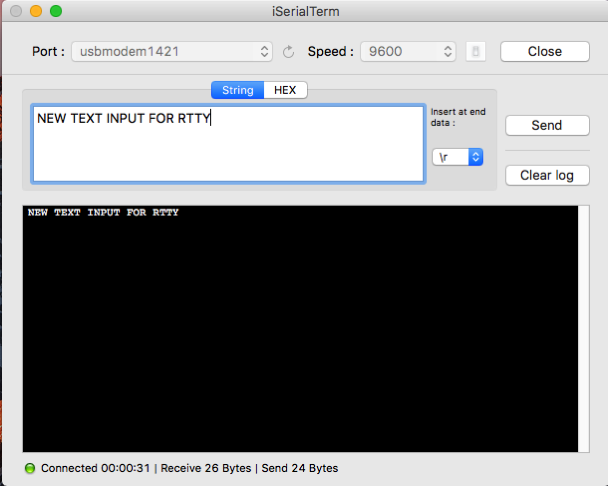
Input text on iSerialTerm, on iMac, connected by USB to Arduino UNO/AD9850

Screen Shot 2017 03 30 at 11 32 20 
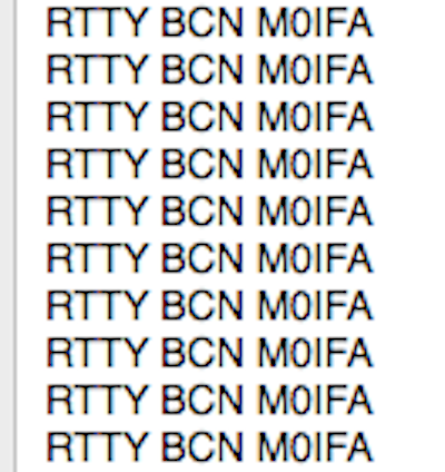
Received text on SDR Concept radio and using HDSDR and MultiMode Cocoa decoder running on my MacBook

Code

// RTTY_TEXT
// V1.0 29-3-17
// thanks to F0GOJ for some of the code
// AD9850
// W_CLK 8
// FQ_UD 9
// DATA 10
// RESET 11
// LCD I2C bus (16x2)
// SDA = A4
// SCL = A5

// ADS9850, LCD and Rotary Encoder libraries
#include "ADS9850.h"
#include "LiquidCrystal_I2C.h"

// AD9850 pins
#define W_CLK 8
#define FQ_UD 9
#define DATA 10
#define RESET 11

// chose address of 0x27 or 0x3F for LCD
//#define LCDADDR 0x27
#define LCDADDR 0x3F
#define LCDCOLS 16
#define LCDROWS 2

// baudot varicode in b4-b0 (sent b0->b4)
char rttyVaricode[59] = {
  4, 22, 17, 5, 18, 0, 11, 26, 30, 9,
  0, 0, 6, 24, 7, 23, 13, 29, 25, 16,
  10, 1, 21, 28, 12, 3, 14, 15, 0, 0,
  0, 19, 0, 24, 19, 14, 18, 16, 22, 11,
  5, 12, 26, 30, 9, 7, 6, 3, 13, 29,
  10, 20, 1, 28, 15, 25, 23, 21, 17
};

#define FIGS 27
#define LTRS 31

// message to send (u.c.)
char msg[40];

// freq in Hz and cHz
double freqHz = 7080000;                              // frequency Hz
double freqChz = 0;                                   // sub freuency cHz

// ads (analog-output digital synthesiser) object
ADS9850 ads;

// lcd object
LiquidCrystal_I2C lcd(LCDADDR, LCDCOLS, LCDROWS);

void setup() {
  // Serial
  Serial.begin(9600);

  // init LCD
  lcd.begin();

  //init AD9850, off to start
  ads.begin(W_CLK, FQ_UD, DATA, RESET);         // initialise synthesiser, pins
  ads.down();

  dispMsg(3, 0, "RTTY TEXT");
  dispFreq(3, 1, freqHz, freqChz, 0);
}

void loop() {
  if (getMsg(msg) == true) {
    dispMsg(3, 1, "Sending Text...  "); // sending
    Serial.println(msg);
    // send message at frequency
    sendMsg(freqHz, freqChz, msg);
    dispMsg(0, 1, "                "); // clear line
  }
  clearBuf(msg);
}

void sendMsg(double fHz, double fChz, char *m) {
  bool figsLtrs;                        // FIGS/LTRS toggle
  char c;

  figsLtrs = 1;                         // start in letter mode

  rttyTxByte(fHz, fChz, 8);             // LFCR for new message
  rttyTxByte(fHz, fChz, 2);

  c = *m++;
  while ( c != '\0') {                 // EOM?
    c = toupper((int)c);               // get char, uppercase

    if (c == 10) {                     // Line Feed 8
      rttyTxByte(fHz, fChz, 8);
    }
    else if (c == 13) {                // Carriage Return 2
      rttyTxByte(fHz, fChz, 2);
    }
    else if (c == 32) {
      rttyTxByte(fHz, fChz, 4);
    }
    else if (c > ' ' && c <= 'Z' ) {   // non-baudot chars sent as blanks 00000
      c = c - ' ';                     // c index 0-58

      if (c <  33) {
        if (figsLtrs == 1) {           // if LTRS
          figsLtrs = 0;                // toggle to FIGS
          rttyTxByte(fHz, fChz, FIGS); // send 27
        }
      }
      else if (figsLtrs == 0) {        // if FIGS
        figsLtrs = 1;                  // toggle to LTRS
        rttyTxByte(fHz, fChz, LTRS);   // send 31
      }

      rttyTxByte(fHz, fChz, rttyVaricode[c]);  // Send the 5 bits word
    }
    c = *m++;  // Next character in string
  }
  ads.down();
}

// send at fHzSymb, fChzSymb, rttyVaricode symb nnnnn
void rttyTxByte(long fHzSymb, long fChzSymb, char symb) {
  int bits, val;

  // build the byte to send
  symb = (symb << 2) + 3;                     // shift two left, add B00000011, makes B0nnnnn11

  for (bits = 7; bits >= 0; bits--) {          // MSB first, b7 -> b0
    val = bitRead(symb, bits); // Read 1 bit
    ads.setFreq(fHzSymb + (170 * val), fChzSymb, 0); // Let's transmit (bit 1 is 170Hz shifted up)
    delay(22); // Gives the baud rate, 22ms per bit
  }
  delay(110);                                  // intersumbol pause
}

// get input msg[] U.C.
bool getMsg(char *m)
{
  char ch;
  int n;

  n = 0;
  if (Serial.available() > 0) {      // if input
    while (Serial.available() > 0) { // get input
      ch = Serial.read();            // use upper case as input
      if (ch == '\n') ch = '\0';     // end of text
      m[n++] = ch;
      delay(20);                     // let USB catch up
    }
    return true;                     // got input
  }
  return false;                      // no input
}

// clear msg and buffer
void clearBuf(char *m) {
  m[0] = '\0';
  while (Serial.available() > 0) Serial.read();
}

// display freq at c)ol, r)ow, f (cHz), d decimal places
void dispFreq(uint8_t c, uint8_t r, float f, float cf, uint8_t d) {
  lcd.setCursor(c, r);
  lcd.print((f + cf / 100.0), d);
  lcd.print("Hz ");
}

// display msg *m at c)ol, r)ow
void dispMsg(uint8_t c, uint8_t r, char *m) {
  lcd.setCursor(c, r);
  lcd.print(m);
}

Tuesday 28 March 2017

BASIC Tech Group - MyNews 33 - More on JT65, Text input

First the block diagrams of my set-up...

JT65 002 Transmit chain

JT65 001 Receive chain

The transmit AD9850 is set to 7076kHz and sends the JT65 symbols on this and 64 higher frequencies spaced 2.69Hz above. The SDR is set to USB on a dial frequency of 7074.725 to give a received audio sync tone at 1000Hz. These tones are sent in 126 time slots of 327ms, a total message transmission time of 47.8sec.

JT65 comms

JT65 requires text input. But there are a few special messages which are not plain text, but cunningly encoded to send more than the limit of 13 characters. Messages such as a reply to a CQ "VK4EF M0IFA R-13" replying to VK4EF with a Roger, and report of 13dB signal strength. But here is a minimum QSO

Screen Shot 2017 03 28 at 12 41 50 Simple JT65 QSO Messages

I have not yet puzzled out how to encode these special messages on the Arduino, so today I can only send max 13 character normal text messages (Upper Case only plus 0-9). My code has been updated to do this, by entering the message on a serial communication app called iSerialTerm (see Mac App store).

Here's a few photos showing what I am doing...

IMG 0896My Desk Top, SDR Concept RX, iMac running HDSDR and JT65-HF programs, AD9850 synthesiser TX

IMG 0895
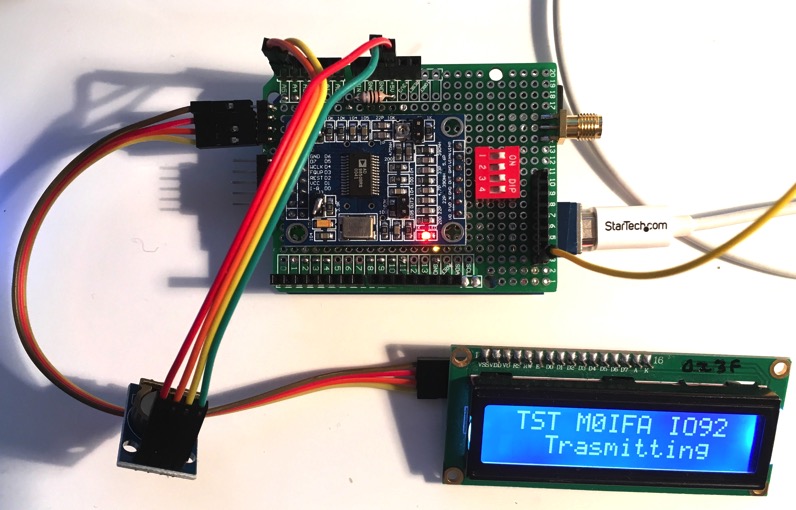
Close up of the RX and TX. Note the tiny piece of yellow wire which is the TX antenna!

Screen Shot 2017 03 29 at 11 04 12 iSerialTerm app running on my MacBook to communicate via Serial with the Arduino UNO. Note 9600 baud, and line end '\n'.

IMG 0898 The message entered on the MacBook, TX waiting for an on-the-minute timing to start sending

IMG 0899The TX sending the message

IMG 0900 The SDR receiver tuning, centre frequency 7050kHz

Screen Shot 2017 03 28 at 12 00 30The HDSDR signal received

Screen Shot 2017 03 28 at 12 04 16
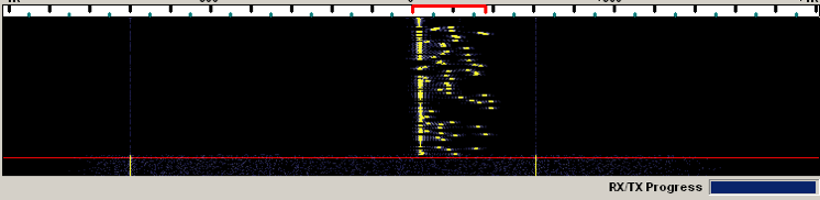
The JT65-HF signal received

Screen Shot 2017 03 28 at 12 03 06 ... and finally the text message received. Voila.

Code

// JT65_ADS_TEXT
// V1.3 29-3-17 added message input/output using iSerialTerm app
// Code based on Feld Hell beacon for Arduino by K6HX
// Timer setup code by LA3PNA.
// AD9850
// W_CLK 8
// FQ_UD 9
// DATA 10
// RESET 11
// LCD I2C bus (16x2)
// SDA = A4
// SCL = A5
// RTC I2C bus
// SDA = A4
// SCL = A5

#include "ADS9850.h"
#include "LiquidCrystal_I2C.h"
#include "Wire.h"

// chose address of 0x27 or 0x3F for LCD
//#define LCDADDR 0x27
#define LCDADDR 0x3F
#define LCDCOLS 16
#define LCDROWS 2

// RTC address
#define RTCADDR 0x68

// Stuff specific to the general (integer) version of the Reed-Solomon codecs
#define MODNN(x) modnn(rs,x)
#define MM (rs->mm)
#define NN (rs->nn)
#define ALPHA_TO (rs->alpha_to)
#define INDEX_OF (rs->index_of)
#define GENPOLY (rs->genpoly)
#define NROOTS (rs->nroots)
#define FCR (rs->fcr)
#define PRIM (rs->prim)
#define IPRIM (rs->iprim)
#define PAD (rs->pad)
#define A0 (NN)

#define TONE_SPACING            269           // ~2.6917 Hz
#define SUBMODE_A               5812         // CTC value for JT65A
#define SYMBOL_COUNT            126

// send indicator
#define LED_PIN                 13

// AD9850 pins
#define W_CLK 8
#define FQ_UD 9
#define DATA 10
#define RESET 11

typedef unsigned int data_t;

/* Reed-Solomon codec control block */
struct rs {
  int mm;              /* Bits per symbol */
  int nn;              /* Symbols per block (= (1<= rs->nn) {
    x -= rs->nn;
    x = (x >> rs->mm) + (x & rs->nn);
  }
  return x;
}


uint8_t jt_code(char c)
{
  /* Validate the input then return the proper integer code */
  // Return 255 as an error code if the char is not allowed

  if (isdigit(c))
  {
    return (uint8_t)(c - 48);
  }
  else if (c >= 'A' && c <= 'Z')
  {
    return (uint8_t)(c - 55);
  }
  else if (c == ' ')
  {
    return 36;
  }
  else if (c == '+')
  {
    return 37;
  }
  else if (c == '-')
  {
    return 38;
  }
  else if (c == '.')
  {
    return 39;
  }
  else if (c == '/')
  {
    return 40;
  }
  else if (c == '?')
  {
    return 41;
  }
  else
  {
    return 255;
  }
}

// timer interrupt veector
ISR(TIMER1_COMPA_vect)
{
  proceed = true;
}

// Reed Soloman encoder by KA9Q
void encode_rs_int(void *p, data_t *data, data_t *parity)
{
  struct rs *rs = (struct rs *)p;

#undef A0
#define A0 (NN) /* Special reserved value encoding zero in index form */


  int i, j;
  data_t feedback;

  memset(parity, 0, NROOTS * sizeof(data_t));

  for (i = 0; i < NN - NROOTS - PAD; i++) {
    feedback = INDEX_OF[data[i] ^ parity[0]];
    if (feedback != A0) {    /* feedback term is non-zero */
#ifdef UNNORMALIZED
      /* This line is unnecessary when GENPOLY[NROOTS] is unity, as it must
         always be for the polynomials constructed by init_rs()
      */
      feedback = MODNN(NN - GENPOLY[NROOTS] + feedback);
#endif
      for (j = 1; j < NROOTS; j++)
        parity[j] ^= ALPHA_TO[MODNN(feedback + GENPOLY[NROOTS - j])];
    }
    /* Shift */
    memmove(&parity[0], &parity[1], sizeof(data_t) * (NROOTS - 1));
    if (feedback != A0)
      parity[NROOTS - 1] = ALPHA_TO[MODNN(feedback + GENPOLY[0])];
    else
      parity[NROOTS - 1] = 0;
  }
}


void free_rs_int(void *p)
{
  struct rs *rs = (struct rs *)p;

  free(rs->alpha_to);
  free(rs->index_of);
  free(rs->genpoly);
  free(rs);
}

// init RS enc, symb size, poly coeff, first root, primative, no roots, padding
void *init_rs_int(int symsize, int gfpoly, int fcr, int prim, int nroots, int pad) {
  struct rs *rs;

  //#undef NULL
  //#define NULL ((void *)0)

  int i, j, sr, root, iprim;

  rs = ((struct rs *)0);
  /* Check parameter ranges */
  if (symsize < 0 || symsize > 8 * sizeof(data_t)) {
    goto done;
  }

  if (fcr < 0 || fcr >= (1 << symsize))
    goto done;
  if (prim <= 0 || prim >= (1 << symsize))
    goto done;
  if (nroots < 0 || nroots >= (1 << symsize))
    goto done; /* Can't have more roots than symbol values! */
  if (pad < 0 || pad >= ((1 << symsize) - 1 - nroots))
    goto done; /* Too much padding */

  rs = (struct rs *)calloc(1, sizeof(struct rs));
  if (rs == NULL)
    goto done;

  rs->mm = symsize;
  rs->nn = (1 << symsize) - 1;
  rs->pad = pad;

  rs->alpha_to = (data_t *)malloc(sizeof(data_t) * (rs->nn + 1));
  if (rs->alpha_to == NULL) {
    free(rs);
    rs = ((struct rs *)0);
    goto done;
  }
  rs->index_of = (data_t *)malloc(sizeof(data_t) * (rs->nn + 1));
  if (rs->index_of == NULL) {
    free(rs->alpha_to);
    free(rs);
    rs = ((struct rs *)0);
    goto done;
  }

  /* Generate Galois field lookup tables */
  rs->index_of[0] = A0; /* log(zero) = -inf */
  rs->alpha_to[A0] = 0; /* alpha**-inf = 0 */
  sr = 1;
  for (i = 0; i < rs->nn; i++) {
    rs->index_of[sr] = i;
    rs->alpha_to[i] = sr;
    sr <<= 1;
    if (sr & (1 << symsize))
      sr ^= gfpoly;
    sr &= rs->nn;
  }
  if (sr != 1) {
    /* field generator polynomial is not primitive! */
    free(rs->alpha_to);
    free(rs->index_of);
    free(rs);
    rs = ((struct rs *)0);
    goto done;
  }

  /* Form RS code generator polynomial from its roots */
  rs->genpoly = (data_t *)malloc(sizeof(data_t) * (nroots + 1));
  if (rs->genpoly == NULL) {
    free(rs->alpha_to);
    free(rs->index_of);
    free(rs);
    rs = ((struct rs *)0);
    goto done;
  }
  rs->fcr = fcr;
  rs->prim = prim;
  rs->nroots = nroots;

  /* Find prim-th root of 1, used in decoding */
  for (iprim = 1; (iprim % prim) != 0; iprim += rs->nn)
    ;
  rs->iprim = iprim / prim;

  rs->genpoly[0] = 1;
  for (i = 0, root = fcr * prim; i < nroots; i++, root += prim) {
    rs->genpoly[i + 1] = 1;

    /* Multiply rs->genpoly[] by  @**(root + x) */
    for (j = i; j > 0; j--) {
      if (rs->genpoly[j] != 0)
        rs->genpoly[j] = rs->genpoly[j - 1] ^ rs->alpha_to[modnn(rs, rs->index_of[rs->genpoly[j]] + root)];
      else
        rs->genpoly[j] = rs->genpoly[j - 1];
    }
    /* rs->genpoly[0] can never be zero */
    rs->genpoly[0] = rs->alpha_to[modnn(rs, rs->index_of[rs->genpoly[0]] + root)];
  }
  /* convert rs->genpoly[] to index form for quicker encoding */
  for (i = 0; i <= nroots; i++)
    rs->genpoly[i] = rs->index_of[rs->genpoly[i]];
done:;

  return rs;
}

uint8_t gray_code(uint8_t c)
{
  return (c >> 1) ^ c;
}

void rs_encode(uint8_t * data, uint8_t * symbols)
{
  unsigned int dat1[12];
  unsigned int b[51];
  unsigned int i;

  // Reverse data order for the Karn codec.
  for (i = 0; i < 12; i++)
  {
    dat1[i] = data[11 - i];
  }

  // Compute the parity symbols
  encode_rs_int(rs, dat1, b);

  // Move parity symbols and data into symbols array, in reverse order.
  for (i = 0; i < 51; i++)
  {
    symbols[50 - i] = b[i];
  }

  for (i = 0; i < 12; i++)
  {
    symbols[i + 51] = dat1[11 - i];
  }
}

void jt65_encode(char * message, uint8_t symbols[SYMBOL_COUNT])
{
  uint8_t i, j, k;

  // Convert all chars to uppercase
  for (i = 0; i < 13; i++)
  {
    if (islower(message[i]))
    {
      message[i] = toupper(message[i]);
    }
  }

  // Collapse multiple spaces down to one

  // Pad the message with trailing spaces
  uint8_t len = strlen(message);
  if (len < 13)
  {
    for (i = len; i < 13; i++)
    {
      message[i] = ' ';
    }
  }

  // Bit packing
  // -----------
  uint8_t c[12];
  uint32_t n1, n2, n3;

  // Find the N values
  n1 = jt_code(message[0]);
  n1 = n1 * 42 + jt_code(message[1]);
  n1 = n1 * 42 + jt_code(message[2]);
  n1 = n1 * 42 + jt_code(message[3]);
  n1 = n1 * 42 + jt_code(message[4]);

  n2 = jt_code(message[5]);
  n2 = n2 * 42 + jt_code(message[6]);
  n2 = n2 * 42 + jt_code(message[7]);
  n2 = n2 * 42 + jt_code(message[8]);
  n2 = n2 * 42 + jt_code(message[9]);

  n3 = jt_code(message[10]);
  n3 = n3 * 42 + jt_code(message[11]);
  n3 = n3 * 42 + jt_code(message[12]);


  // Pack bits 15 and 16 of N3 into N1 and N2,
  // then mask reset of N3 bits
  n1 = (n1 << 1) + ((n3 >> 15) & 1);
  n2 = (n2 << 1) + ((n3 >> 16) & 1);
  n3 = n3 & 0x7fff;

  // Set the freeform message flag
  n3 += 32768;

  c[0] = (n1 >> 22) & 0x003f;
  c[1] = (n1 >> 16) & 0x003f;
  c[2] = (n1 >> 10) & 0x003f;
  c[3] = (n1 >> 4) & 0x003f;
  c[4] = ((n1 & 0x000f) << 2) + ((n2 >> 26) & 0x0003);
  c[5] = (n2 >> 20) & 0x003f;
  c[6] = (n2 >> 14) & 0x003f;
  c[7] = (n2 >> 8) & 0x003f;
  c[8] = (n2 >> 2) & 0x003f;
  c[9] = ((n2 & 0x0003) << 4) + ((n3 >> 12) & 0x000f);
  c[10] = (n3 >> 6) & 0x003f;
  c[11] = n3 & 0x003f;

  // Reed-Solomon encoding
  // ---------------------
  uint8_t s[63];
  k = 0;

  rs_encode(c, s);

  // Interleaving
  // ------------
  uint8_t d[63];
  uint8_t d1[7][9];

  // Fill temp d1 array
  for (i = 0; i < 9; i++)
  {
    for (j = 0; j < 7; j++)
    {
      d1[i][j] = s[(i * 7) + j];
    }
  }

  // Interleave and translate back to 1D destination array
  for (i = 0; i < 7; i++)
  {
    for (j = 0; j < 9; j++)
    {
      d[(i * 9) + j] = d1[j][i];
    }
  }

  // Gray Code
  // ---------
  uint8_t g[63];

  for (i = 0; i < 63; i++)
  {
    g[i] = gray_code(d[i]);
  }

  // Merge with sync vector
  // ----------------------
  const uint8_t sync_vector[126] =
  { 1, 0, 0, 1, 1, 0, 0, 0, 1, 1, 1, 1, 1, 1, 0, 1, 0, 1, 0, 0,
    0, 1, 0, 1, 1, 0, 0, 1, 0, 0, 0, 1, 1, 1, 0, 0, 1, 1, 1, 1,
    0, 1, 1, 0, 1, 1, 1, 1, 0, 0, 0, 1, 1, 0, 1, 0, 1, 0, 1, 1,
    0, 0, 1, 1, 0, 1, 0, 1, 0, 1, 0, 0, 1, 0, 0, 0, 0, 0, 0, 1,
    1, 0, 0, 0, 0, 0, 0, 0, 1, 1, 0, 1, 0, 0, 1, 0, 1, 1, 0, 1,
    0, 1, 0, 1, 0, 0, 1, 1, 0, 0, 1, 0, 0, 1, 0, 0, 0, 0, 1, 1,
    1, 1, 1, 1, 1, 1
  };

  j = 0;

  for (i = 0; i < 126; i++)
  {
    if (sync_vector[i])
    {
      symbols[i] = 0;
    }
    else
    {
      symbols[i] = g[j] + 2;
      j++;
    }
  }

}

// get time from RTC, convert bcd to decimal
void getRTC()
{
  // Reset the register pointer
  Wire.beginTransmission(RTCADDR);
  byte zero = 0x00;
  Wire.write(zero);
  Wire.endTransmission();

  // request 1st 3 bytes from the RTC address
  Wire.requestFrom(RTCADDR, 3);

  // get the s/m/h time data
  sec = bcdToDec(Wire.read());
  mns = bcdToDec(Wire.read());
  hrs = bcdToDec(Wire.read() & 0b111111); // mask 24 hour time bit
}

// Convert binary coded decimal to normal decimal numbers
byte bcdToDec(byte val)
{
  return ( (val / 16 * 10) + (val % 16) );
}

// get input msg[] U.C.
bool getMsg(char *m)
{
  char ch;
  int n;

  n = 0;
  if (Serial.available() > 0) {      // if input
    while (Serial.available() > 0) { // get input
      ch = Serial.read();            // use upper case as input
      if (ch == '\n') ch = '\0';     // end of text
      m[n++] = ch;
      delay(20);                     // let USB catch up
    }
    return true;                     // got input
  }
  return false;                      // no input
}

// clear msg and buffer
void clearBuf(char *m) {
  m[0] = '\0';
  while (Serial.available() > 0) Serial.read();
}

// display msg *m at c)ol, r)ow
void dispMsg(uint8_t c, uint8_t r, char *m)
{
  lcd.setCursor(c, r);
  lcd.print(m);
}

// display freq at c)ol, r)ow, f (cHz), d decimal places
void dispFreq(uint8_t c, uint8_t r, float f, float cf, uint8_t d) {
  lcd.setCursor(c, r);
  lcd.print((f + cf / 100.0), d);
  lcd.print("Hz ");
}

// display time at col, row
void dispTime(byte c, byte r) {
  lcd.setCursor(c, r);
  if (hrs < 10)
    lcd.print("0");
  lcd.print(hrs);
  lcd.print(":");
  if (mns < 10)
    lcd.print("0");
  lcd.print(mns);
  lcd.print(":");
  if (sec < 10)
    lcd.print("0");
  lcd.print(sec);
}

Thursday 23 March 2017

BASIC Tech Group - MyNews 32 - JT65 on Arduino

A quick look on 40m shows a lot of JT65 comms taking place. Here's the picture as received by the WEB SDR at Hack Green

Screen Shot 2017 03 23 at 16 29 09

And the decode using the program JT64-HF running under Wine on my iMac. By the way I use the expensive, but TERRIFIC program called Loopback to send audio from my Safari browser to JT64-HF, works a treat.

Screen Shot 2017 03 23 at 16 31 51

I am working on a Arduino Sketch to generate JT65, but am a bit bamboozled by the Reed Solomon encoding at he moment and things aren't working...

Arduino

So I have ported the code Si5351_JT65 downloaded from the internet, and have adapted it for the AD9850 Synthesiser. It was quite terrifying as it contains lines and lines of code that I simply do not understand - especially the part doing the Reed-Solomon error correction calculations.

Anyway these are the results. First a photo fo the Arduino Shield, note that I have plugged in an RTC (DS3231) module to give me real time and allow message start on the minute,

IMG 0889

And here are the SDR received signals using HDSDR running under Wine on my iMac, and feeding the audio to JT65-HF also running under Wine on the iMac.

Screen Shot 2017 03 25 at 17 38 39

Screen Shot 2017 03 25 at 17 38 48

I have yet to code the messagess that are commonly used in JT65 QSOs for CQ and replies.

Code

Download

BASIC Tech Group - MyNews 31 - LCD voltmeter

Here is a very simple LCD display voltmeter, for 0-5V inputs - do NOT exceed as will destroy the Arduino!!!

It was written to be used as a digital voltmeter for measuring the output of a simple RF Probes.

Screen Shot 2017 03 23 at 15 57 30

The output of such a probe is the peak-to-peak RF voltage, minus any loss due to the diode forward drop. So its not an accurate measurement.

On the other hand the sketch has been written such that for an input of 0.225V (1mW in to 50R) it displays 0dB, and will then show the relative log (dB) of your voltage measurement...

IMG 0874 Code

// LCD_V using LCD to display analog voltage
// V1 10-3-17
// LCD I2C bus (16x2)
// GND - GND
// VCC - 5V
// SDA - A4
// SCL - A5

#include 
#include 

// chose address of 0x27 or 0x3F for LCD
#define LCDADDR 0x27
//#define LCDADDR 0x3F
#define LCDCOLS 16
#define LCDROWS 2

// lcd object
LiquidCrystal_I2C lcd(LCDADDR, LCDCOLS, LCDROWS);

void setup() {

  lcd.begin();

  lcd.print("   VOLTMETER   ");
}

void loop() {
  int Ain;                          // 0-1023 input
  double Vin, calc, dB;

  Ain = analogRead(A0);
  Vin = Ain * (5.0 / 1023.0);       // convert to volts

  lcd.setCursor(0, 1);              // clear display line
  lcd.print("                ");
  
  lcd.setCursor(1, 1);              // volts
  lcd.print(Vin, 3);
  lcd.print("V     ");

  if (Vin > 0) {                    // if not zero dB
    dB = 10 * log10(Vin * Vin / 0.05);
    lcd.setCursor(9, 1);
    lcd.print(dB, 1);
    lcd.print("dB");
  }


  delay(500);
}

Friday 10 March 2017

BASIC Tech Group - MyNews 30 - AD9850 RTTY Beacon

To round off this session on generating various digital transmissions with the AD9850 synthesiser and the Arduino, here is the RTTY one.

Beacon Tx

IMG 0812

SDR RX

Screen Shot 2017 03 10 at 12 25 42

Received signals, using MacOS MultiMode Cooca software

Screen Shot 2017 03 10 at 12 26 38

And here's the code

// BCN_RTTY Beacon for RTTY
// V1.1 9-3-17
// thanks to F0GOJ for some of the code
// AD9850
// W_CLK 8
// FQ_UD 9
// DATA 10
// RESET 11
// LCD I2C bus (16x2)
// SDA = A4
// SCL = A5

// ADS9850, LCD and Rotary Encoder libraries
#include "ADS9850.h"
#include "LiquidCrystal_I2C.h"

// AD9850 pins
#define W_CLK 8
#define FQ_UD 9
#define DATA 10
#define RESET 11

// chose address of 0x27 or 0x3F for LCD
//#define LCDADDR 0x27
#define LCDADDR 0x3F
#define LCDCOLS 16
#define LCDROWS 2

// baudot varicode in b4-b0 (sent b0->b4)
char rttyVaricode[59] = {
  4, 22, 17, 5, 18, 0, 11, 26, 30, 9,
  0, 0, 6, 24, 7, 23, 13, 29, 25, 16,
  10, 1, 21, 28, 12, 3, 14, 15, 0, 0,
  0, 19, 0, 24, 19, 14, 18, 16, 22, 11,
  5, 12, 26, 30, 9, 7, 6, 3, 13, 29,
  10, 20, 1, 28, 15, 25, 23, 21, 17
};

#define FIGS 27
#define LTRS 31

// beacon message to send (u.c.)
char msg[] = "RTTY BCN M0IFA";

// freq in Hz and cHz
double freqHz = 7080000;                              // frequency Hz
double freqChz = 0;                                   // sub freuency cHz

// repeat time (ms)
unsigned long repeat = 2000;

// ads (analog-output digital synthesiser) object
ADS9850 ads;

// lcd object
LiquidCrystal_I2C lcd(LCDADDR, LCDCOLS, LCDROWS);

void setup() {
  // init LCD
  lcd.begin();

  //init AD9850
  ads.begin(W_CLK, FQ_UD, DATA, RESET);         // initialise synthesiser, pins

  dispMsg(0, 0, "RTTY");
  dispFreq(5, 0, freqHz, freqChz, 0); // display FREQ xxxxxx.xx kHz col 5 row 0
  dispMsg(0, 1, msg); // out msg
}

void loop() {
  // send message at frequency
  sendMsg(freqHz, freqChz, msg);

  delay(repeat); // repeat
}

void sendMsg(double fHz, double fChz, char *m) {
  bool figsLtrs;                        // FIGS/LTRS toggle
  char c;

  figsLtrs = 1;                         // start in letter mode
  
  c = *m++;
  while ( c != '\0') {                 // EOM?
    c = toupper((int)c);               // get char, uppercase
    if (c == 10) {                     // Line Feed 8
      rttyTxByte(fHz, fChz, 8);
    }
    else if (c == 13) {                // Carriage Return 2
      rttyTxByte(fHz, fChz, 2);
    }
    else if (c == 32) {
      rttyTxByte(fHz, fChz, 4);
    }
    else if (c > ' ' && c <= 'Z' ) {   // non-baudot chars sent as blanks 00000
      c = c - ' ';                     // c index 0-58
      
      if (c <  33) {
        if (figsLtrs == 1) {           // if LTRS
          figsLtrs = 0;                // toggle to FIGS
          rttyTxByte(fHz, fChz, FIGS); // send 27
        }
      }
      else if (figsLtrs == 0) {        // if FIGS
        figsLtrs = 1;                  // toggle to LTRS
        rttyTxByte(fHz, fChz, LTRS);   // send 31
      }
      
      rttyTxByte(fHz, fChz, rttyVaricode[c]);  // Send the 5 bits word
    }
    c = *m++;  // Next character in string
  }
  ads.down();
}

// send at fHz, fChz, rttyVaricode s(ymb nnnnn
void rttyTxByte(long fHzSymb, long fChzSymb, char symb) {
  int bits, val;

  // build the byte to send
  symb = (symb << 2) + 3;                     // shift two left, add B00000011, makes B0nnnnn11

  for (bits = 7; bits >= 0; bits--) {          // MSB first, b7 -> b0
    val = bitRead(symb, bits); // Read 1 bit
    ads.setFreq(fHzSymb + (170 * val), fChzSymb, 0); // Let's transmit (bit 1 is 170Hz shifted up)
    delay(22); // Gives the baud rate, 22ms per bit
  }
  delay(110);                                  // intersumbol pause
}

// display freq at c)ol, r)ow, f (cHz), d decimal places
void dispFreq(uint8_t c, uint8_t r, float f, float cf, uint8_t d) {
  lcd.setCursor(c, r);
  lcd.print((f + cf / 100.0), d);
  lcd.print("Hz ");
}

// display msg *m at c)ol, r)ow
void dispMsg(uint8_t c, uint8_t r, char *m) {
  lcd.setCursor(c, r);
  lcd.print(m);
}
I am not too happy with this code as it seems VERY timing sensitive.

Tuesday 7 March 2017

BASIC Tech Group - MyNews 29 - AD9850 PSK31 Beacon

Following up from the last project, the CW Beacon - I have re-written the code to use a set of Varicode for PSK31 symbols and to switch the frequency output by phase (0 or 180deg).

IMG 0807

Screen Shot 2017 03 10 at 11 03 16Screen Shot 2017 03 10 at 11 01 33

Reception on Mac cocoaModem software

This is the Arduino code.

Code

// BCN_PSK Beacon for PSK31
// V2 7-3-17
// thanks to F0GOJ for principles of the code
// AD9850
// W_CLK 8
// FQ_UD 9
// DATA 10
// RESET 11
// LCD I2C bus (16x2)
// SDA = A4
// SCL = A5

// ADS9850 and LCD I2C libraries
#include "ADS9850.h"
#include "LiquidCrystal_I2C.h"

// AD9850 pins
#define W_CLK 8
#define FQ_UD 9
#define DATA 10
#define RESET 11

// chose address of 0x27 or 0x3F for LCD
#define LCDADDR 0x27
//#define LCDADDR 0x3F
#define LCDCOLS 16
#define LCDROWS 2

// init freqs
#define STARTHZ 7070000
#define STARTCHZ 0

#define BAUD 32

// psk varicode and index of length
int pskVaricode[2][128] = {
  { 683, 731, 749, 887, 747, 863, 751, 765, 767, 239,
    29, 879, 733, 31, 885, 939, 759, 757, 941, 943,
    859, 875, 877, 855, 891, 893, 951, 853, 861, 955,
    763, 895, 1, 511, 351, 501, 475, 725, 699, 383,
    251, 247, 367, 479, 117, 53, 87, 431, 183, 189,
    237, 255, 375, 347, 363, 429, 427, 439, 245, 445,
    493, 85, 471, 687, 701, 125, 235, 173, 181, 119,
    219, 253, 341, 127, 509, 381, 215, 187, 221, 171,
    213, 477, 175, 111, 109, 343, 437, 349, 373, 379,
    685, 503, 495, 507, 703, 365, 735, 11, 95, 47,
    45, 3, 61, 91, 43, 13, 491, 191, 27, 59, 15, 7, 63,
    447, 21, 23, 5, 55, 123, 107, 223, 93, 469, 695,
    443, 693, 727, 949
  },
  { 10, 10, 10, 10, 10, 10, 10, 10, 10,
    8, 5, 10, 10, 5, 10, 10, 10, 10, 10,
    10, 10, 10, 10, 10, 10, 10, 10, 10,
    10, 10, 10, 10, 1, 9, 9, 9, 9, 10, 10,
    9, 8, 8, 9, 9, 7, 6, 7, 9, 8, 8, 8, 8,
    9, 9, 9, 9, 9, 9, 8, 9, 9, 7, 9, 10,
    10, 7, 8, 8, 8, 7, 8, 8, 9, 7, 9, 9,
    8, 8, 8, 8, 8, 9, 8, 7, 7, 9, 9, 9, 9,
    9, 10, 9, 9, 9, 10, 9, 10, 4, 7, 6, 6,
    2, 6, 7, 6, 4, 9, 8, 5, 6, 4, 3, 6, 9,
    5, 5, 3, 6, 7, 7, 8, 7, 9, 10, 9, 10, 10, 10
  }
};

// beacon message to send
char msg[] = "Beacon de M0IFA...";

// freq in Hz and cHz
long freqHz = STARTHZ;                              // frequency Hz
long freqChz = STARTCHZ;                            // sub freuency cHz

// repeat time (ms)
long repeat = 2000;

// ads (analog-output digital synthesiser) object
ADS9850 ads;

// lcd object
LiquidCrystal_I2C lcd(LCDADDR, LCDCOLS, LCDROWS);

void setup() {
  // init LCD
  lcd.begin();

  //init AD9850
  ads.begin(W_CLK, FQ_UD, DATA, RESET);         // initialise synthesiser, pins

  dispMsg(0, 0, "BCNPSK");
  dispFreq(7, 0, freqHz + freqChz / 100, 2); // display FREQ xxxxxx.xx kHz col 5 row 0
  dispMsg(0, 1, msg); // out msg
}

void loop() {
  // send message at frequency
  sendMsg(freqHz, freqChz, msg);


  delay(repeat); // repeat
}

// send message
void sendMsg(long fHz, long fChz, char m[]) {
  int c, vCode, bits;
  uint8_t phase;

  phase = 0x00;
  // Idle is zeroes so only phase inversion
  for (int n = 0; n < BAUD; n++) {
    phase = phase ^ 0x10;                // XOR toggle  b4 1 0000 <-> 0 0000
    ads.setFreq(fHz, fChz, phase);
    delay((961 + BAUD) / BAUD);          // fix baud rate
  }

  c = 0;
  while (m[c] != '\0') {
    vCode = pskVaricode[0][m[c]];         // Get PSK varicode
    bits = pskVaricode[1][m[c]];          // Get PSK varicode length

    vCode <<= 2;                          // add 00 on lsb for char space
    bits += 1;                            // msb to 0

    //send char in psk
    for (int n = bits; n >= 0; n--) {   // msb 1st, bits to 0
      if (bitRead(vCode, n) == 0)       // 0 | 1 ?
        phase = phase ^ 0x10;           // XOR toggle b4 1 0000 <-> 0 0000
      ads.setFreq(fHz, fChz, phase);    // transmit
      delay((961 + BAUD) / BAUD);       // set speed
    }
    c++;
  }

  phase = 0x00;
  // Idle is zeroes so only phase inversion
  for (int n = 0; n < BAUD; n++) {
    phase = phase ^ 0x10;                // XOR toggle  b4 1 0000 <-> 0 0000
    ads.setFreq(fHz, fChz, phase);
    delay((961 + BAUD) / BAUD);          // fix baud rate
  }
  
  // end of message
  ads.down();
}

// display freq at c)ol, r)ow, f (cHz), to d decimal places (kHz)
void dispFreq(uint8_t c, uint8_t r, uint64_t f, uint8_t d) {
  lcd.setCursor(c, r);
  lcd.print((float)f / 1000, d); // convert to float & kHz
  lcd.print("kHz ");
}

// display msg *m at c)ol, r)ow
void dispMsg(uint8_t c, uint8_t r, char *m) {
  lcd.setCursor(c, r);
  lcd.print(m);
}

Saturday 4 March 2017

BASIC Tech Group - MyNews 28 - AD9850 CW Beacon

Here are the details of a CW Beacon I made, based on the AD9850 Arduino shield. Code below, insert your own message in the code and upload. Can easily be modified to read in the message from your keyboard and send it. PSK31 version underway, watch this space

IMG 0806

Code

// CWTX Beacon
// V1.1 4-3-17
// Thanks to F0GOJ for some of the code
// AD9850
// W_CLK 8
// FQ_UD 9
// DATA 10
// RESET 11
// LCD I2C bus (16x2)
// SDA = A4
// SCL = A5

// ADS9850, LCD and Rotary Encoder libraries
#include "ADS9850.h"
#include "LiquidCrystal_I2C.h"

// AD9850 pins
#define W_CLK 8
#define FQ_UD 9
#define DATA 10
#define RESET 11

// xtal calibration
#define CALIBRATE 124999500

// chose address of 0x27 or 0x3F for LCD
#define LCDADDR 0x27
//#define LCDADDR 0x3F
#define LCDCOLS 16
#define LCDROWS 2


// morse varicode index 0-58 is SP to Z
// [code in a byte][7-n bits to send, MSB first]
// e.g. 192 = 1100 0000, top 4 bits 7-4 = --.. or Z
// 0 = dot, 1 = dash
static int morseVaricode[2][59] = {
  { 0, 212, 72, 0, 144, 0, 128, 120, 176, 180,
    0, 80, 204, 132, 84, 144, 248, 120, 56, 24,
    8, 0, 128, 192, 224, 240, 224, 168, 0, 136,
    0, 48, 104, 64, 128, 160, 128, 0, 32, 192,
    0, 0, 112, 160, 64, 192, 128, 224, 96, 208,
    64, 0, 128, 32, 16, 96, 144, 176, 192
  },
  { 7, 6, 5, 0, 4, 0, 4, 6, 5, 6,
    0, 5, 6, 6, 6, 5, 5, 5, 5, 5,
    5, 5, 5, 5, 5, 5, 6, 6, 0, 5,
    0, 6, 6, 2, 4, 4, 3, 1, 4, 3,
    4, 2, 4, 3, 4, 2, 2, 3, 4, 4,
    3, 3, 1, 3, 4, 3, 4, 4, 4
  }
};

// beacon message to send (u.c.)
char msg[] = "YOUR MESSAGE GOES HERE";

// freq is fHz + cHz, 7030000
long fHz = 7030000;                             // frequency Hz
long cHz = 0;                                 // sub freuency cHz

//speed WPM
int wpm = 10;

// ads (analog-output digital synthesiser) object
ADS9850 ads;

// lcd object
LiquidCrystal_I2C lcd(LCDADDR, LCDCOLS, LCDROWS);

void setup() {

  // init LCD
  lcd.begin();
  
  //init AD9850
  ads.begin(W_CLK, FQ_UD, DATA, RESET);         // initialise synthesiser, pins

  // calibrate to xtal actual frequency
  ads.calibrate(CALIBRATE);

  dispMsg(0, 0, "cwTX");
  dispFreq(5, 0, fHz+cHz/100, 2); // display FREQ xxxxxx.xx kHz col 5 row 0
  dispMsg(0, 1, msg); // out msg
}

void loop() {
  cwTx(fHz, cHz, msg, wpm);                     // send CW message

  delay(5000);                                  //repeat 5sec
}

// send CW on freqHz+freqChz, message, WPM
void cwTx(long freqHz, long freqChz, char *stringCw, int cwWpm) {
  byte nbBits, bitVal;                          // nobits to send 7-nbBits
  int d;                                        // varicode data

  // calculate dot time
  int dotTime = 1200 / cwWpm;                   // Duration of 1 dot

  // get 1st char
  int c = *stringCw++;                          // read char

  //send chars in CW
  while (c != '\0') {
    c = toupper(c);                             // u.c.just in case
    
    if (c == ' ') {                             // catch ASCII SP
      c = c - ' ';                              // convert c-32 to index 0 - 58
      ads.down();
      delay(dotTime * 7);
    }
    else if (c > ' ' && c < ']') {
      c = c - ' ';                              // convert c-32 to index 0 - 58
      d = morseVaricode[0][c];                  // get CW varicode data
      nbBits = morseVaricode[1][c];             // get CW varicode length
      if (nbBits != 0) {                        // if not invalid morse
                                                // characters # % < >
        for (int b = 7; b > 7 - nbBits; b--) {  // Send CW character
                                                // (0 for dot, 1 for dash) MSB first
          bitVal = bitRead(d, b);               // look up varicode bit
          ads.setFreq(freqHz, freqChz, 0);      // transmit for
          delay(dotTime + 2 * dotTime * bitVal);// dot length or a dash length
                                                // dash = 3 times the dot
          ads.down();                           // synth off for
          delay(dotTime);                       // 1 dot space between dots|dashes
        }
      }
      ads.down();                               // synth off 3 dots
      delay(dotTime * 3);                       // between characters in a word
    }
    c = *stringCw++;                            // next character in string
  }
  ads.down();                                   // No more transmission
}

// display freq at c)ol, r)ow, f (cHz), to d decimal places (kHz)
void dispFreq(uint8_t c, uint8_t r, uint64_t f, uint8_t d) {
  lcd.setCursor(c, r);
  lcd.print((float)f / 1000, d); // convert to float & kHz
  lcd.print("kHz ");
}

// display msg *m at c)ol, r)ow
void dispMsg(uint8_t c, uint8_t r, char *m)
{
  lcd.setCursor(c, r);
  lcd.print(m);
}


Friday 3 March 2017

BASIC Tech Group - MyNews 27 - AD9850 Analog Digital Synthesiser

There are basically three types of frequency synthesiser 1. The Pahse Locked Loop, 2. The purely digital counter - like the Si5351, and 3. the Synthesised sine wave output digital types, like the AD9850.

The AD9850 is able to generate sine wave output from below 1MHz to above 30MHz with low harmonic content. This design for an Arduino shield for an Arduino Uno build a VFO from 1-30MHz with frequency steps of 10Hz to 1MHz.

IMG 0801

Here is the VFO inked up to my RF METER and showing an output of 1mW/-3dBM/161mV into a 50R load, yes I know 1mW is not 161mV, but is 225mV, but it's rounded to one decimal place.

And here's a few other photos

IMG 0802

IMG 0803

IMG 0804

The shield has outputs on two of the 8 ins connector, one as a VFO and one as a TX, and alos an output via the SMA connector. The outputs can be selected by the red switch. The connections on the right are for a rotary encoder (frequency) and push button (step size) for tuning and for an LCD I2C display.

Software

Two pieces of software have been written for the AD9850. The first is a ibary with ".h" and ".cpp? files. The ADS9850.h & .cpp files must be put in a library folder called ADS9850 in your "libraries" folder.

// Arduino Library for AD9850 frequency synthesiser module
// V1.1 27-2-17 Antony Watts, M0IFA
// frequency in Hz and cHz
// W_CLK, FQ_UD, DATA, RESET to any pins
// void begin(int W_CLK, int FQ_UD, int DATA, int RESET); intialise pins and reset AD9850
// void setFreq(double Hz, float Chz, uint8_t p); set frequency(Hz) and centi-freq(Chz)
// void calibrate(double calHz); change xtal frequency from standard 125MHz to new value
// void down(); power down, power up with setFreq()

#ifndef ADS9850_H
#define ADS9850_H

#include

#define ADS_XTAL 125000000

class ADS9850 {

	public:
		ADS9850();

		void begin(int W_CLK, int FQ_UD, int DATA, int RESET);
		void setFreq(unsigned long Hz, unsigned long Chz, uint8_t phase);
		void calibrate(unsigned long calHz);
                void down();

	private:
		int _W_CLK;
		int _FQ_UD;
		int _DATA;
		int _RESET;

		unsigned long _calFreq;

                void update(unsigned long fr, uint8_t ph);
		void pulse(int _pin);

};

#endif
// Arduino Library for AD9850 frequency synthesiser module
// V1.1 27-2-17 Antony Watts, M0IFA
// frequency in Hz and cHz, phase in 5bits 0x00 - 0x1F
// W_CLK, FQ_UD, DATA, RESET to any pins
// void begin(int W_CLK, int FQ_UD, int DATA, int RESET); intialise pins and reset AD9850
// void setFreq(double Hz, float Chz, uint8_t p); set frequency(Hz) and centi-freq(Chz)
// void calibrate(double calHz); change xtal frequency from standard 125MHz to new value
// void down(); power down, power up with setFreq()

#include "Arduino.h"
#include "ADS9850.h"

ADS9850::ADS9850() {

}

void ADS9850::begin(int W_CLK, int FQ_UD, int DATA, int RESET) {
	_W_CLK = W_CLK;
	_FQ_UD = FQ_UD;
	_DATA = DATA;
	_RESET = RESET;
	_calFreq = ADS_XTAL;

	pinMode(_W_CLK, OUTPUT);
	pinMode(_FQ_UD, OUTPUT);
	pinMode(_DATA, OUTPUT);
	pinMode(_RESET, OUTPUT);

	pulse(_RESET);
	pulse(_W_CLK);
	pulse(_FQ_UD);
}

void ADS9850::update(unsigned long fr, uint8_t ph) {

        shiftOut(_DATA, _W_CLK, LSBFIRST, fr);
	shiftOut(_DATA, _W_CLK, LSBFIRST, fr >> 8);
	shiftOut(_DATA, _W_CLK, LSBFIRST, fr >> 16);
	shiftOut(_DATA, _W_CLK, LSBFIRST, fr >> 24);

	shiftOut(_DATA, _W_CLK, LSBFIRST, ph & 0xFF);

        pulse(_FQ_UD);
}

void ADS9850::setFreq(unsigned long Hz, unsigned long Chz, uint8_t phase) {
        uint32_t tuneHz, tuneChz;

	Chz /= 100.0;

	tuneHz = Hz * pow(2, 32) / _calFreq;
        tuneChz = Chz * pow(2, 32) / _calFreq;

        phase = phase << 3;

        update(tuneHz + tuneChz, phase);
}


void ADS9850::calibrate(unsigned long calXtal) {
	_calFreq = calXtal;
}

void ADS9850::down() {

	pulse(_FQ_UD);

	update(0x00000000, 0x04);
}

void ADS9850::pulse(int _pin) {
	digitalWrite(_pin, HIGH);
	digitalWrite(_pin, LOW);
}

And the Arduino sketch is

// VFO_DDS freq synth, 100kHz to 150MHz square wave
// V2.1 2-3-17
// output G0
// freq steps 10Hz, 100Hz, 1kHz, 10kHz, 100kHz, 1MHz
// AD9850
// W_CLK 8
// FQ_UD 9
// DATA 10
// RESET 11
// LCD I2C bus (16x2)
// SDA = A4
// SCL = A5
// rotary encoder pins
// DT = 2
// CLK = 3
// SW = 4

// ADS9850, LCD and Rotary Encoder libraries
#include "ADS9850.h"
#include "LiquidCrystal_I2C.h"
#include "Rotary.h"

// AD9850 pins
#define W_CLK 8
#define FQ_UD 9
#define DATA 10
#define RESET 11

// chose address of 0x27 or 0x3F for LCD
#define LCDADDR 0x27
//#define LCDADDR 0x3F
#define LCDCOLS 16
#define LCDROWS 2

// chose pin 2,3 or 3,2 for encoder
//#define DT 2
#define DT 3
//#define CLK 3
#define CLK 2
#define SW 4

// xtal calibration
#define CALIBRATE 124999500

// min freq 100kHz, max 30MHz (cHz)
#define FREQMIN 100000
#define FREQMAX 30000000

// ads (analog-output digital synthesiser) object
ADS9850 ads;

// lcd object
LiquidCrystal_I2C lcd(LCDADDR, LCDCOLS, LCDROWS);

// Encoder object
Rotary enc = Rotary(DT, CLK);

// phase coding, 0-180 in 11.25deg steps
uint8_t ph[] = {0x00, 0x01, 0x02, 0x04, 0x08, 0x10};

// initial settings
volatile long freq = 7100000; // (Hz) start frequency 7.1MHz
volatile long centiFreq = 0;  // (cHz) additional 0cHz
volatile long freqStep = 10; // (Hz) init 10Hz freqStep
uint8_t phase = ph[0]; // init phase

// freq change flag
volatile bool freqChange;

void setup() {
  // encoder, button pins
  pinMode(DT, INPUT_PULLUP);
  pinMode(CLK, INPUT_PULLUP);
  pinMode(SW, INPUT_PULLUP);

  // setup interrupts from DT or CLK for tuning
  attachInterrupt(digitalPinToInterrupt(DT), freqTune, CHANGE);
  attachInterrupt(digitalPinToInterrupt(CLK), freqTune, CHANGE);

  // enable interrupts
  interrupts();

  // init LCD
  lcd.begin();

  // init AD9850
  ads.begin(W_CLK, FQ_UD, DATA, RESET);

  // calibrate to xtal actual frequency
  ads.calibrate(CALIBRATE);

  freqOut(freq, centiFreq, phase); // Hz, output freq(Hz) & centi freq(cHz), phase
  freqChange = false;

  dispMsg(0, 0, "VFO"); // init title
  dispFreq(5, 0, freq, 2); // display FREQ xxxxxx.xx kHz col 5 row 0
  dispMsg(0, 1, "Step"); // init title
  dispfreqStep(freqStep, 5, 1); // display freqStep xxxxHz|kHz col 5, row 1
}

void loop() {
  // freqStep?
  if (button()) {
    dispfreqStep(freqStep, 5, 1); // display freq step
  }
  if (freqChange) {
    freqOut(freq, centiFreq, phase);
    freqChange = false;
    dispFreq(5, 0, freq, 2); // display freq
  }
}

// ISR - encoder interrupt service routine
void freqTune() {
  unsigned char result;

  result = enc.process();
  if (result == DIR_CW && freq < FREQMAX) {
    freq += freqStep;
    freqChange = true;
  }
  else if (result == DIR_CCW && freq > FREQMIN) {
    freq -= freqStep;
    freqChange = true;
  }
}

// change freqStep, 10Hz to 1MHz
bool button() {
  if (digitalRead(SW) == LOW) { // button pressed?
    while (!digitalRead(SW)); // wait for release
    if (freqStep == 1000000) freqStep = 10; // back to 10Hz
    else freqStep = freqStep * 10; // or increase by x10
    return true;
  }
  else {
    return false;
  }
}

// Output VFO Freq f (Hz) + cf (cHz), phase ph
void freqOut(unsigned long f, float cf, uint8_t ph) {
  ads.setFreq(f, cf, ph);
}

// display freq at c)ol, r)ow, f (cHz), to d decimal places (kHz)
void dispFreq(uint8_t c, uint8_t r, uint64_t f, uint8_t d) {
  lcd.setCursor(c, r);
  lcd.print((float)f / 1000, d); // convert to float & kHz
  lcd.print("kHz ");
}

// display freqStep s (Hz) at c)ol, r)ow
void dispfreqStep(uint64_t s, byte c, byte r)
{
  lcd.setCursor(c, r);
  switch (s) // display freqStep
  {
    case 10:
      lcd.print("10Hz     ");
      break;
    case 100:
      lcd.print("100Hz    ");
      break;
    case 1000:
      lcd.print("1kHz     ");
      break;
    case 10000:
      lcd.print("10kHz    ");
      break;
    case 100000:
      lcd.print("100kHz   ");
      break;
    case 100000000:
      lcd.print("1MHz     ");
      break;
  }
}

// display msg *m at c)ol, r)ow
void dispMsg(uint8_t c, uint8_t r, char *m)
{
  lcd.setCursor(c, r);
  lcd.print(m);
}