Wednesday 23 September 2015

Concept Session 4 - ENC LCD

The 4th Concept session covers the prototyping of a VFO with Rotary Encoder tuning and LCD frequency display.

Concept S4 ENC LCD 007

This rotary encoder has 20 steps for each rotation, at each step the signal outputs change as shown, changes depend on the direction the encoder is turned. A library "Rotate.h" sorts out the changes and reports the result.

Concept S4 ENC LCD 008

This is the wiring diagram. The first sketch used is called My_VFO_ROTARY, this displays the VFO frequency on the Monitor as you turn the Encoder. It changes in fixed 100Hz steps - very simple.

// My_VFO_ROTARY controls the freq by rotary encoder, freq display on monitor
// button changes band
// Si5351 I2C bus
// SDA = A4
// SCL = A5
// LCD I2C bus
// SDA = A4
// SCL = A5
// rotary encoder pins
// DT = 2
// CLK = 3
// SW = 4

// I2C, Si5351, LCD and rotary Encoder libraries
#include "Wire.h"
#include "si5351.h"
#include "Rotary.h"

// tuning freq STEPS (cHz), 100Hz
#define STEPS 10000

// rotary Encoder pins 2 & 3 (DT & CLK), band change pin 4 (SW)
#define DT 2
#define CLK 3
#define SW 4

// dds object
Si5351 dds;

// rotary Encoder object
Rotary rot = Rotary(DT, CLK);

// start frequencies (cHz), band names
uint32_t freqStart[3] = {
  710000000, 1014000000, 1410000000
};

// band, freq (cHz)
byte band = 0;
uint32_t freq = freqStart[band];

void setup() {
  Serial.begin(9600);

  // init dds si5351 module, "0" = default 25MHz XTAL
  dds.init(SI5351_CRYSTAL_LOAD_8PF, 0);

  // set 8mA output drive
  dds.drive_strength(SI5351_CLK0, SI5351_DRIVE_8MA);

  // enable VFO output CLK0, disable CLK1 & 2
  dds.output_enable(SI5351_CLK0, 1);
  dds.output_enable(SI5351_CLK1, 0);
  dds.output_enable(SI5351_CLK2, 0);

  // encoder, button, RX, TX, band and XMIT pins
  pinMode(DT, INPUT_PULLUP);
  pinMode(CLK, INPUT_PULLUP);
  pinMode(SW, INPUT_PULLUP);

  freqOut(freq); // output freq
  dispFreq(freq); // display freq
}

void loop() {
  // tune?
  if (tune()) {
    freqOut(freq);
    dispFreq(freq);
  }

  // band?
  if (button()) {
    freq = freqStart[band];
    freqOut(freq);
    dispFreq(freq);
  }
}

// tune?
bool tune() {
  unsigned char dir; // tuning direction CW/CCW

  // turned?
  dir = rot.process(); // read encoder
  if (dir != DIR_NONE) { // turned?
    if (dir == DIR_CW) freq += STEPS; // increment freq +/- STEPS
    if (dir == DIR_CCW) freq -= STEPS;
    return true;
  }
  return false;
}

// band?
bool button() {
  if (digitalRead(SW) == LOW) { // button pressed?
    while (!digitalRead(SW)); // wait for release
    if (band == 2) band = 0; // loop
    else band++;
    return true;
  }
  return false;
}

// frequency (in cHz) for VFO, on CLK0
void freqOut(uint32_t f) {
  dds.set_freq(f, 0ULL, SI5351_CLK0); // converted to cHz
}

// display freq in cHz
void dispFreq(uint32_t f) {
  Serial.print("My VFO = ");
  Serial.print((float)f / 100000, 1); // convert to float for print function
  Serial.println(" kHz");
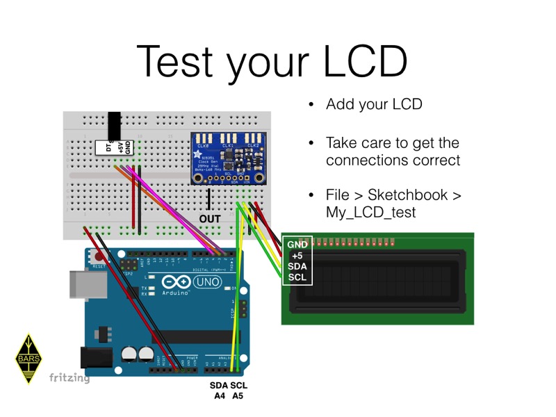
}


Next we add the LCD display, this connects via an I2C bus connection (note some displays seem to have address 0x0x27 others 0x3F, if one doesn't work try the other).

Concept S4 ENC LCD 014

Wire up your LCD

Concept S4 ENC LCD 016

Concept S4 ENC LCD 019

This is the code for tuning with the encoder

// My_VFO_ROTARY_LCD controls the freq by rotary encoder, freq display on LCD
// button changes band
// Si5351 I2C bus
// SDA = A4
// SCL = A5
// LCD I2C bus
// SDA = A4
// SCL = A5
// rotary encoder pins
// DT = 2
// CLK = 3
// SW = 4

// I2C, Si5351, LCD and rotary Encoder libraries
#include "Wire.h"
#include "si5351.h"
#include "Rotary.h"
#include "LiquidCrystal_I2C.h"

// tuning freq STEPS (cHz), 100Hz
#define STEPS 10000

// rotary Encoder pins 2 & 3 (DT & CLK), band change pin 4 (SW)
#define DT 2
#define CLK 3
#define SW 4

// dds object
Si5351 dds;

// rotary Encoder object
Rotary rot = Rotary(DT, CLK);

// lcd object
LiquidCrystal_I2C lcd(0x27, 16, 2);

// start frequencies (cHz), band names
uint32_t freqStart[3] = {
  710000000, 1014000000, 1410000000};

// band, freq (cHz)
byte band = 0;
uint32_t freq = freqStart[band];

void setup() {
        
  // init LCD & backlight on
  lcd.init();
  lcd.backlight();
  
  // init dds si5351 module, "0" = default 25MHz XTAL
  dds.init(SI5351_CRYSTAL_LOAD_8PF, 0);

  // set 8mA output drive
  dds.drive_strength(SI5351_CLK0, SI5351_DRIVE_8MA);

  // enable VFO output CLK0, disable CLK1 & 2
  dds.output_enable(SI5351_CLK0, 1);
  dds.output_enable(SI5351_CLK1, 0);
  dds.output_enable(SI5351_CLK2, 0);

  // encoder, button, RX, TX, band and XMIT pins
  pinMode(DT, INPUT_PULLUP);
  pinMode(CLK, INPUT_PULLUP);
  pinMode(SW, INPUT_PULLUP);
  
  freqOut(freq); // output freq
  dispFreq(freq); // display freq
}

void loop() {
  // tune?
  if (tune()) {
    freqOut(freq);
    dispFreq(freq);
  }
  
  // band?
  if (button()) {
    freq = freqStart[band];
    freqOut(freq);
    dispFreq(freq);
  }
}

// tune?
bool tune() {
  unsigned char dir; // tuning direction CW/CCW

  // turned?
  dir = rot.process(); // read encoder
  if (dir != DIR_NONE) { // turned?
    if (dir == DIR_CW) freq += STEPS; // increment freq +/- STEPS
    if (dir == DIR_CCW) freq -= STEPS;
    return true;
  }
  return false;
}

// band?
bool button() {
  if (digitalRead(SW) == LOW) { // button pressed?
    while (!digitalRead(SW)); // wait for release
    if (band == 2) band = 0; // loop
    else band++;
    return true;
  }
  return false;
}

// frequency (in cHz) for VFO, on CLK0
void freqOut(uint32_t f) {
    dds.set_freq(f, 0ULL, SI5351_CLK0); // converted to cHz
}

// display freq in cHz
void dispFreq(uint32_t f) {
  lcd.setCursor(0, 0);
  lcd.print("VFO                 ");
  lcd.setCursor(4, 0);
  lcd.print((float)f / 100000, 1); // convert to float for print function
  lcd.setCursor(13, 0);
  lcd.print("kHz");
}


In a future session we will be building a VFO PCB shield. Some tools are needed for this

Concept S4 ENC LCD 026

Thursday 17 September 2015

Concept Session 3 - Eagle

I have not documented the session about Eagle PCB design software here. As I have already put a 3 part description on this blog.

Have a look at 2015 February to find the information.

Wednesday 9 September 2015

Concept Session 2 - VFO & RTC

Here are the slides for the next Concept Session 2. This will cover the breadboarding of the VFO and RTC modules. Concept will conclude with the construction two shields for the Arduino UNO

Concept S2 VFO RTC 003

For the whole system to work there has to be a standard interconnect between shields. This is

Concept S2 VFO RTC 004

The important part is the new connector on the left, carrying the RF signals - VFO, RX and TX.

Receivers and Transmitters

Concept S2 VFO RTC 007

Concept S2 VFO RTC 008

A VFO needs three things, a VFO and BFO output and a quadrature I & Q output. Thus our Shield will look like this.

Concept S2 VFO RTC 009

Concept S2 VFO RTC 010

The VFO is based around the Si5351, which has 3 RF outputs, Outputs 1 & 2 are for VFO & BFO, output 3 is connected to a SN74AC74 as a Johnson counter to generate the IQ signals for an SDR.

Concept S2 VFO RTC 012

Concept S2 VFO RTC 013

The RTC is also a pre-built module using the DS3231 RTC chip and a backup battery.

Concept S2 VFO RTC 014

Build a VFO

Concept S2 VFO RTC 015

Code

This code runs the Si5351, with frequency display on the Arduion Monitor and new frequency input on the keyboard.

// My_VFO_KB is a keyboard input/screen display VFO
// Starter kit VFO using Si5351 module, freq in cHz
// Si5351 I2C bus
// SDA = A4
// SCL = A5

// I2C and Si5351 Libraries
#include "Wire.h"
#include "si5351.h"

// create dds object
Si5351 dds;

// start frequency (cHz)
uint32_t freq = 700000000; // 7MHz
uint32_t prevFreq = freq;

// setup runs once on upload
void setup(){
  // start serial (monitor "NEWLINE" & 9600 baud)
  Serial.begin(9600);
  
  // init dds si5351 module, "0" = default 25MHz XTAL
  dds.init(SI5351_CRYSTAL_LOAD_8PF, 0);

  // set 8mA output drive
  dds.drive_strength(SI5351_CLK0, SI5351_DRIVE_8MA);

  // enable VFO output CLK0, disable CLK1 & 2
  dds.output_enable(SI5351_CLK0, 1);
  dds.output_enable(SI5351_CLK1, 0);
  dds.output_enable(SI5351_CLK2, 0);
  
  freqOut(freq); // output freq
  dispFreq(freq); // display freq in Hz
}

void loop(){
   freq = getIn(); // get input freq cHz
   
  // new freq?
  if(freq != prevFreq)
  {
    freqOut(freq); // output freq
    dispFreq(freq); // display in Hz
    prevFreq = freq; // remember as previous freq
  }
}

// freq output in cHz on CLK0
void freqOut(uint32_t freq){
    dds.set_freq(freq, 0, SI5351_CLK0); // cHz
}

// get input Hz, return cHz
uint32_t getIn(){
  uint32_t in;
  
  while(Serial.available() > 0) // flush buffer
    Serial.read();
    
  while(Serial.available() == 0) // wait for input
    in = Serial.parseInt(); // read input in Hz and parse to integer
   
  return in * 100UL; // return in cHz
}

// display frequency on monitor
void dispFreq(uint32_t f){
  // display freq
  Serial.print("My_VFO = ");
  Serial.print((float)f / 100, 0); // convert to float & display in Hz
  Serial.println(" Hz");
}


Build an RTC

Concept S2 VFO RTC 020

Concept S2 VFO RTC 021

Concept S2 VFO RTC 022

Code

These two sketches first set the RTC time, then display it on an I2C connected LCD display

// My_RTC set
// enter YYMMDDwHHMMSS on Monitor, w = week day
// note 1 = mon. 01 = Jan
// hit ENTER exactly on the time you want to set

#include "Wire.h"
#include "DS3231.h"
#include "LiquidCrystal_I2C.h"

// LCD address, cols, rows
#define LCDADDR 0x27
#define LCDCOLS 16
#define LCDROWS 2

// RTC address
#define RTCADDR 0x68

// LCD object
LiquidCrystal_I2C lcd(LCDADDR, LCDCOLS, LCDROWS);

// rtc object
DS3231 rtc;

// RTC time and date
byte Second, prevSecond, Minute, Hour, DoW, Date, prevDate, Month, Year;

bool gotString;

void setup() {
  // Start the serial port
  Serial.begin(9600);

  // init LCD & backlight on
  lcd.init();
  lcd.backlight();

  // Start the I2C interface
  Wire.begin();

  dispMsg(0, 0, "Enter time:           ");
  dispMsg(0, 1, "\"YYMMDDwHHMMSS\"");

  gotString = false;
}

void loop() {
  char inString[20] = "";
  byte j = 0;
  
  while (!gotString) {
    if (Serial.available()) {
      inString[j] = Serial.read();

      if (inString[j] == '\n') {
        gotString = true;

        Serial.println(inString);

        // convert ASCII codes to bytes
        Year = ((byte)inString[0] - 48) * 10 + (byte)inString[1] - 48;
        Month = ((byte)inString[2] - 48) * 10 + (byte)inString[3] - 48;
        Date = ((byte)inString[4] - 48) * 10 + (byte)inString[5] - 48;
        DoW = ((byte)inString[6] - 48);
        Hour = ((byte)inString[7] - 48) * 10 + (byte)inString[8] - 48;
        Minute = ((byte)inString[9] - 48) * 10 + (byte)inString[10] - 48;
        Second = ((byte)inString[11] - 48) * 10 + (byte)inString[12] - 48;

        rtc.setYear(Year);
        rtc.setMonth(Month);
        rtc.setDate(Date);
        rtc.setDoW(DoW);
        rtc.setHour(Hour);
        rtc.setMinute(Minute);
        rtc.setSecond(Second);
      }
      j += 1;
    }
  }

  getRTC(); // get time
  
  if(Second != prevSecond) {
      dispTime(4, 1); // display it, if changed
      prevSecond = Second;
  }
  if(Date != prevDate) {
    dispDate(0, 0);
    prevDate = Date;
  }
}

// get time from RTC, convert bcd to decimal
void getRTC() {
  // Reset the RTC register pointer
  Wire.beginTransmission(RTCADDR);
  byte zero = 0x00;
  Wire.write(zero);
  Wire.endTransmission();

  // request 7 bytes from the RTC address
  Wire.requestFrom(RTCADDR, 7);

  // get the time data
  Second = bcdToDec(Wire.read()); // 0 - 59
  Minute = bcdToDec(Wire.read()); // 0 - 59
  Hour = bcdToDec(Wire.read() & 0b111111); //mask 12/24 bit
  DoW = bcdToDec(Wire.read()); //0 - 6 = Sunday - Saturday
  Date = bcdToDec(Wire.read()); // 1 - 31
  Month = bcdToDec(Wire.read()); // 0 = jan
  Year = bcdToDec(Wire.read()); // 20xx
}

// Convert binary coded decimal to normal decimal numbers
byte bcdToDec(byte val) {
  return ( (val / 16 * 10) + (val % 16) );
}

// display char msg at col c, row r
void dispMsg(uint8_t c, uint8_t r, char *m) {
  lcd.setCursor(c, r);
  lcd.print(m);
}

// display date and time
void dispDate(byte c, byte r) {
  lcd.clear();
  
  lcd.setCursor(c, r);
  switch (DoW) {
    case 1:
      lcd.print("Mon");
      break;
    case 2:
      lcd.print("Tue");
      break;
    case 3:
      lcd.print("Wed");
      break;
    case 4:
      lcd.print("Thu");
      break;
    case 5:
      lcd.print("Fri");
      break;
    case 6:
    lcd.print("Sat");
    break;
    case 7:
    lcd.print("Sun");
    break;
  }

  lcd.print(" ");
  lcd.print(Date);

  lcd.print(" ");
  switch (Month)
  {
    case 1:
      lcd.print("Jan");
      break;
    case 2:
      lcd.print("Feb");
      break;
    case 3:
      lcd.print("Mar");
      break;
    case 4:
      lcd.print("Apr");
      break;
    case 5:
      lcd.print("May");
      break;
    case 6:
      lcd.print("Jun");
      break;
    case 7:
      lcd.print("Jul");
      break;
    case 8:
      lcd.print("Aug");
      break;
    case 9:
      lcd.print("Sep");
      break;
    case 10:
      lcd.print("Oct");
      break;
    case 11:
      lcd.print("Nov");
      break;
    case 12:
      lcd.print("Dec");
      break;
  }
  lcd.print(" ");
  lcd.print("20");
  lcd.print(Year);
}

void dispTime(byte c, byte r) {
  lcd.setCursor(c, r);
  if (Hour < 10)
    lcd.print("0");
  lcd.print(Hour);
  lcd.print(":");
  if (Minute < 10)
    lcd.print("0");
  lcd.print(Minute);
  lcd.print(":");
  if (Second < 10)
    lcd.print("0");
  lcd.print(Second);
}


// My_RTC_LCD
// display time on LCD I2C

// CONNECTIONS
// RTC DS1307 or DS3231
// SCL = A5
// SDA = A4
// I2C address 0x57
// ------
// display LCD I2C
// o A5 SCL
// o A4 SDA
// o +5
// o GND
// I2C address 0x27

// libraries
#include "Wire.h"
#include "LiquidCrystal_I2C.h"

// RTC I2C address
#define RTCADDR 0x68

// LCD
#define LCDADDR 0x27
#define LCDCOLS 16
#define LCDROWS 2

// LCD object
LiquidCrystal_I2C lcd(LCDADDR, LCDCOLS, LCDROWS);

// RTC time and date
byte Second, prevSecond, Minute, Hour, DoW, Date, prevDate, Month, Year;

void setup() {
  // initialise the wire library for I2C comms
  Wire.begin();

  // init LCD & backlight on
  lcd.init();
  lcd.backlight();

  getRTC();
  dispDate(0, 0); //  display date & time
  dispTime(4, 1);
  prevSecond = Second; // save current second & date
  prevDate = Date;
}

void loop() {
  getRTC(); // get time
  if (Second != prevSecond) {
    dispTime(4, 1); // display it, if changed
    prevSecond = Second;
  }
  if (Date != prevDate) {
    dispDate(0, 0);
    prevDate = Date;
  }
}

// get time from RTC, convert bcd to decimal
void getRTC() {
  // Reset the RTC register pointer
  Wire.beginTransmission(RTCADDR);
  byte zero = 0x00;
  Wire.write(zero);
  Wire.endTransmission();

  // request 7 bytes from the RTC address
  Wire.requestFrom(RTCADDR, 7);

  // get the time data
  Second = bcdToDec(Wire.read()); // 0 - 59
  Minute = bcdToDec(Wire.read()); // 0 - 59
  Hour = bcdToDec(Wire.read() & 0b111111); // mask 12/24 bit
  DoW = bcdToDec(Wire.read()); //0 - 6 = Sunday - Saturday
  Date = bcdToDec(Wire.read()); // 1 - 31
  Month = bcdToDec(Wire.read()); // 0 = jan
  Year = bcdToDec(Wire.read()); // 20xx
}

// Convert binary coded decimal to normal decimal numbers
byte bcdToDec(byte val) {
  return ( (val / 16 * 10) + (val % 16) );
}

// display date and time
void dispDate(byte c, byte r) {
  lcd.clear();
  
  lcd.setCursor(c, r);
 switch (DoW) {
    case 1:
      lcd.print("Mon");
      break;
    case 2:
      lcd.print("Tue");
      break;
    case 3:
      lcd.print("Wed");
      break;
    case 4:
      lcd.print("Thu");
      break;
    case 5:
      lcd.print("Fri");
      break;
    case 6:
    lcd.print("Sat");
    break;
    case 7:
    lcd.print("Sun");
    break;
  }

  lcd.print(" ");
  lcd.print(Date);

  lcd.print(" ");
  switch (Month)
  {
    case 1:
      lcd.print("Jan");
      break;
    case 2:
      lcd.print("Feb");
      break;
    case 3:
      lcd.print("Mar");
      break;
    case 4:
      lcd.print("Apr");
      break;
    case 5:
      lcd.print("May");
      break;
    case 6:
      lcd.print("Jun");
      break;
    case 7:
      lcd.print("Jul");
      break;
    case 8:
      lcd.print("Aug");
      break;
    case 9:
      lcd.print("Sep");
      break;
    case 10:
      lcd.print("Oct");
      break;
    case 11:
      lcd.print("Nov");
      break;
    case 12:
      lcd.print("Dec");
      break;
  }
  lcd.print(" ");
  lcd.print("20");
  lcd.print(Year);
}

void dispTime(byte c, byte r) {
  lcd.setCursor(c, r);
  if (Hour < 10)
    lcd.print("0");
  lcd.print(Hour);
  lcd.print(":");
  if (Minute < 10)
    lcd.print("0");
  lcd.print(Minute);
  lcd.print(":");
  if (Second < 10)
    lcd.print("0");
  lcd.print(Second);
}


Concept S2 VFO RTC 026