I have lashed out and bought on of those incredibly low cost "45W PA" kits!

These are rated at 45W output, but this is definitely pushing it as far as the safe operating area of the IRF510 output transistors. Anyway I don't want 45W, so I will redesign for 20-30W output at 12V supply.
CALCULATION
The output load for 20W for each transistor is
Vdd^2 / 2 * Pout, or 12^2/2*20 = 3.6R.
Next the output is the usual 50R, so we have to match 3.6 to 50R. The formula for the turns ratio is
Zout/Zin = (tout/tin)^2. or
tout = tin * sqrt(Zout / Zin), or 2 * sqrt(50 / 3.6) = 7.5
So the MOSFET side input turns are 2+2 turns, and the output turns are about 7 turns.
So I need a transformer with this turns ratiot on a suitable binocular ferrite core.
PLAN
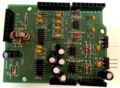
My plan is to try to shoehorn this 20W PA and some LPFs (from QRP Labs for 20/30/40m) into a small box similar to those I have used before (see previous posts). It will be a squeeze as it will need also switching repays and a Arduino Nanocomputer for control and an OLED band display, I might even try to squeeze in a power meter.
Sunday 29 April 2018
Output transformer for a 20-30W PA
Thursday 26 April 2018
Driving an OLED 1.3" display - Arduino functions
Over the last year I have developed a header file which provides a set of standard functions based on the u8g2 library for display on an OLED display (I use a 1.3" one with an SH1106 controller and I2C interface to A4-SDA & A5 SCL pins.)
Here is the Oled.h manual
And here is the code.
Put this header file in a folder called "Oled" in your Arduino's libraries folder and include it in your sketches.
Sunday 22 April 2018
Progress - QRP SDR Transceiver
I made a boo, boo and destroyed the Nanocomputer on the first DDS I built - wired up the Rotary Encoder wrong way round! Thus shorting out the +5V supply! But I have rebuilt it now. And this is what I have now, not finished, but the Transceiver is complete, and the DDS is working, but not yet the /4 74AC74 Johnson counter...
The Transceiver
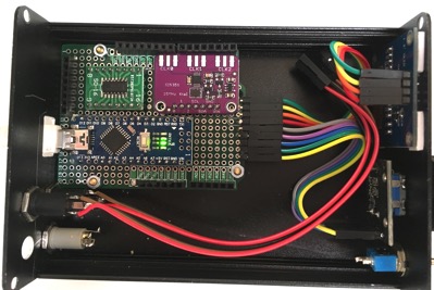
The DDS, 74AC74 in place but not wired yet
The display, and software which drives the DDS
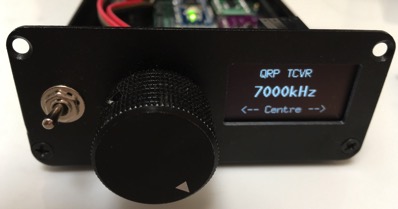
The QRP TCVR is expected to have all of 50mW output! and will need a decent PA to use it on the 40, 30 & 20m bands.
Sunday 15 April 2018
Update and tidy up of AD9851 WSPR code
My code for using an AD9851 synthesiser, with a DS3231 Real Time Clock, to send WSPR messages has always been a bit messy. Now I have tidied it up.
Note that my code sends out signals on Arduino pins A0 & A1 which are used to control the LPF band switching in a PA. You can see the codes sent over a 4 pin 3.5mm jack in the code. At the PA these switch the LPF relays to chose the correct band, as well as switching from RX/TX modes.
The code uses four libraries, my own AD9851.h and Oled.h, and public Rotary.h & WsprMessage.h.
My libraries are listed below. All my sketches and libraries can be downloaded from the blogpost above.
CODE
// WSPR with AD9851 synth
// V4.0 18-4-15 simplify code to remove wspr message copy
//   enter callsign, MH locator and Power in the code below

// HEADERS & LIBRARIES
#include "Oled.h"
#include "ADS9851.h"
#include "Rotary.h"
#include "WsprMessage.h"

// CONNECTIONS
#define RESET 8      // AD9851
#define DATA 9
#define FQ_UD 10
#define W_CLK 11
#define CLK 2        // ENC
#define DT 3
#define SW 4         // button


// PARAMETERS
// RTC I2C address
#define RTCADDR 0x68
// PA modes
#define RX 0
#define TX40 1
#define TX30 2
#define TX20 3

// xtal calibration, WSPR symbollength adj, orginal 682
#define CALIBRATE 180000000
#define SYMBOLLENGTH 684

// OBJECTS
// create AD9851 object
ADS9851 ads;

// Encoder object
Rotary enc = Rotary(DT, CLK);

// GLOBAL VARIABLES
// RTC Data, Decimal
byte sec, mns, hrs;
byte dow;
byte dy, mth, yr;

// repeat TX interval (sec)
uint8_t repeat;

// WSPR data
char callsign[10] = " M0IFA";         // your callsign 6 char (SP first if needed)
char loc_short[5] = "IO92";           // your short locator (read from EEPROM)
char power[5] = "30";                 // TX power in dBm, 30 = 1W

// band
byte band = 1; // band 1 = 40m

// table of band frequencies 0 RX, 1-3 TX40, 30, 20
double freqTable[] = {
  0, 7040100, 10140200, 14097100};

// WSPR cHz Freq for symbols 0, 1, 2, 3.
// = 145.48 x 0, 1, 2 and 3
double freqChz[] = {0.0, 146.0, 291.0, 437.0};

// WSPR Frequency & phase
double freqHz = freqTable[band];
volatile double freqStep = 10;         // (Hz) freqStep 10Hz
uint8_t phase = 0;                     // phase

// TX flag
bool tx;

// freq change flag
bool freqChange;

// Data from WsprMessage
unsigned char *sym;                   // ptr to symbol vector in WsprMessage.h

// SETUP
void setup() {
  Serial.begin(9600);

  // encoder
  pinMode(DT, INPUT_PULLUP);
  pinMode(CLK, INPUT_PULLUP);

  // button
  pinMode(SW, INPUT_PULLUP);

  // jack PA control outputs
  pinMode(A0, OUTPUT);
  pinMode(A1, OUTPUT);

  // setup interrupts from DT or CLK for tuning
  PCICR |= (1 << PCIE2);
  PCMSK2 |= (1 << PCINT18) | (1 << PCINT19);
  sei();

  // oled init, sets I2C addr to 0x3C
  oled.begin();

  // ads begin
  ads.begin(W_CLK, FQ_UD, DATA, RESET);

  // calibrate to xtal actual frequency
  ads.calibrate(CALIBRATE);

  // create WSPR message, define MSG_SIZE and get pointer to symbols
  WsprMessage WsprMessage(callsign, loc_short, atoi(power));
  sym = WsprMessage.symbols;            // get address ptr to symbols

  repeat = 4;                           // repeat every 4 min, must be even number
                                        // Should be random 4-20 or so

  tx = false;                           // display flag

  // PA init TX40
  setPA(band);  // PA S/W requires that band must be initialised by TX command,
                // followed by return to passive RX
  delay(1000);
  setPA(RX);

  freqChange = false;
}

void loop() {
  // get time & display
  readRTC();
  dispUpdate();

  if (button()) {                // button updates band choice
    if (band < 3) band += 1;
    else band = 1;
    if (band == 1) setPA(TX40); // 40m
    if (band == 2) setPA(TX30); // 30m
    if (band == 3) setPA(TX20); // 20m
    delay(500);
    setPA(RX);
    freqHz = freqTable[band];
    dispUpdate();
  }

  if (freqChange) {
    freqChange = false;
    dispUpdate();
  }

  // send WSPR?
  if (mns % repeat == 0 && sec == 0)
  {
    // send
    tx = true;                  // display msgTxt
    if (band == 1) setPA(TX40); // 40m
    if (band == 2) setPA(TX30); // 30m
    if (band == 3) setPA(TX20); // 20m
    dispUpdate();
    sendWspr(SYMBOLLENGTH);
    tx = false;              // display time
    setPA(RX);
  }
}

// BUTTON
bool button() {
  if (digitalRead(SW) == LOW) { // button pressed?
    while (!digitalRead(SW)); // wait for release
    return true;
  }
  else {
    return false;
  }
}

// ENCODER/INTERRUPT
// ISR - encoder interrupt service routine
ISR(PCINT2_vect) {
  unsigned char result;

  result = enc.process();
  if (result == DIR_CW ) {
    freqHz += freqStep;
    freqChange = true;
  }
  else if (result == DIR_CCW) {
    freqHz -= freqStep;
    freqChange = true;
  }
}


//send the WSPR msg
void sendWspr(int SymbolLength) {
  // Send WSPR Message
  for  (int s = 0; s < MSG_SIZE; s++) {                    // For all symbols, MSG_SIZE in WsprMessage.h
    ads.setFreq(freqHz, freqChz[sym[s]], phase);           // transmit frequency
    delay(SymbolLength);                                   // symbol timing
  }
  ads.down();                                              // disable output
}

// Convert BCD to decimal numbers
byte bcdToDec(byte val) {
  return ( (val / 16 * 10) + (val % 16) );
}

// READ RTC
void readRTC() {
  // Reset the RTC register pointer
  Wire.beginTransmission(RTCADDR);
  Wire.write(0x00);
  Wire.endTransmission();

  // request 7 bytes from the RTC address
  Wire.requestFrom(RTCADDR, 7);

  // get the time date
  sec = bcdToDec(Wire.read()); // 0 - 59
  mns = bcdToDec(Wire.read()); // 0 - 59
  hrs = bcdToDec(Wire.read() & 0b111111); // mask 12/24 bit
  dow = bcdToDec(Wire.read()); // 0 = Sunday
  dy  = bcdToDec(Wire.read()); // 1 - 31
  mth = bcdToDec(Wire.read()); // 0 = jan
  yr  = bcdToDec(Wire.read()); // ..yy
}

// SET PA MODE
// modes 0, 1, 2, 3 output on A1, A0, active LOW
void setPA(int m) {
  // set mode
  switch (m) {
    case 0:
      digitalWrite(A1, HIGH);
      digitalWrite(A0, HIGH);    // RX
      break;
    case 1:
      digitalWrite(A1, HIGH);
      digitalWrite(A0, LOW);    // TX40
      break;
    case 2:
      digitalWrite(A1, LOW);
      digitalWrite(A0, HIGH);   // TX30
      break;
    case 3:
      digitalWrite(A1, LOW);
      digitalWrite(A0, LOW);    // TX20
      break;
  }

}


// picture loop, display init data
void dispUpdate() {
  oled.firstPage();
  do {
    // initial display
    dispMsg(50, 0, "WSPR");
    dispFreq(15, 15, freqHz, freqChz[0], 2); // display frequency
    if (tx == true) {
      dispMsg(10, 35, callsign);
      dispMsg(55, 35, loc_short);
      dispMsg(85, 35, power);
    }
    else {
      dispTime(40, 35, hrs, mns, sec);
    }
    dispMsg(20, 50, "Every");
    dispNum(70, 50, repeat, 0);
    dispMsg(85, 50, "min");
  } while ( oled.nextPage() );
}
LIBRARIESPut AD9851.h & AD9851.cpp in a folder named AD9851, and put Oled.h in a folder named Oled both in your Arduino "libraries" folder
AD9851.h
// Arduino Library for AD9851 frequency synthesiser module, with 30MHz clock
// V1.2 4-9-17 Antony Watts, M0IFA, code update
// frequency in Hz and cHz
// functions
// void begin(int W_CLK, int FQ_UD, int DATA, int RESET); intialise pins and reset AD9850
// void setFreq(double Hz, double Chz, uint8_t p); set frequency(Hz) and centi-freq(Chz)
//   phase coding, 0-180 in 11.25deg steps 0x00, 0x01, 0x02, 0x04, 0x08, 0x10
// void calibrate(double calHz); change xtal frequency from standard 125MHz to new value
// void down(); power down on, x6 remains on b00000101

#ifndef ADS9851_H
#define ADS9851_H

#include "Arduino.h"

#define ADS_XTAL 180000000.0

class ADS9851 {

    public:
        ADS9851();

        void begin(int W_CLK, int FQ_UD, int DATA, int RESET);
        void setFreq(double Hz, double Chz, uint8_t phase);
        void calibrate(double calHz);
        void down();

    private:
		int _W_CLK;
		int _FQ_UD;
		int _DATA;
		int _RESET;

		double _calFreq;

        void update(uint32_t d, uint8_t p);
		void pulse(int _pin);

};

#endif
AD9851.cpp
// Arduino Library for AD9851 frequency synthesiser module, with 30MHz clock
// V1.2 4-9-17 Antony Watts, M0IFA, pulser code update
// frequency in Hz and cHz
// W_CLK, FQ_UD, DATA, RESET to (e.g.) D11, D10, D9 & D8
// functions
// void begin(int W_CLK, int FQ_UD, int DATA, int RESET); reset, serial, down
// void setFreq(double Hz, double Chz, uint8_t p); set f(Hz) and cHz(Chz),
//   p)hase in steps 0x00, 0x01, 0x02, 0x04, 0x08, 0x10 (11.5, 22.5, 45. 90, 180deg)
// void calibrate(double calHz); correct xtal frequency from standard 180MHz (30MHz x6)
// void down(); freq zero, power down (power up with setFreq())

#include "Arduino.h"
#include "ADS9851.h"

// constructor
ADS9851::ADS9851() {

}

// init calFreq, pins, reset & serial mode
void ADS9851::begin(int W_CLK, int FQ_UD, int DATA, int RESET) {
	_W_CLK = W_CLK;
	_FQ_UD = FQ_UD;
	_DATA = DATA;
	_RESET = RESET;

	_calFreq = ADS_XTAL;

	pinMode(_W_CLK, OUTPUT); // outputs default to LOW
	pinMode(_FQ_UD, OUTPUT);
	pinMode(_DATA, OUTPUT);
	pinMode(_RESET, OUTPUT);

	pulse(_RESET); // reset, parallel mode, ptr to W0

        pulse(_W_CLK); // switch to serial mode, xxxxx011 wired on d2-d0

        down(); // init/clear freq & phase registers, power down
}

// write 40 bits, 4x8 freq + 8 control & phase
void ADS9851::update(uint32_t fW, uint8_t cP) {
    for (int i=0; i <4 ; i++, fW >>= 8) {
       shiftOut(_DATA, _W_CLK, LSBFIRST, fW); // output 32 freq bits
    }
    shiftOut(_DATA, _W_CLK, LSBFIRST, cP); // output 8 control & phase bits

    pulse(_FQ_UD);
}

// calculate 32 freq bits, convert double to to uint32_t, set PD off & x6, update
void ADS9851::setFreq(double f, double cf, uint8_t p) {
     uint32_t delta;

	delta = (uint32_t)((f + cf/100.0) * 4294967296.0 / _calFreq);
	p = p << 3; // PD off = ppppp000
        bitSet(p, 0); // ppppp001 set x6 REFCLK on
	update(delta, p);
}

// clear freq & phase registers
void ADS9851::down() {
        update(0x00000000, 0x04); // freq zero, ppppp100 set PD on, x6 REFCLK off
}


// pulse a pin LOW-HIGH-LOW
void ADS9851::pulse(int _pin) {
        digitalWrite(_pin, LOW);
	digitalWrite(_pin, HIGH);
        digitalWrite(_pin, LOW);
}

// load a new value for _calFreq
void ADS9851::calibrate(double calXtal) {
	_calFreq = calXtal;
}
OLED<br />
// Oled.h
// V2.0 18-4-5 added UL numbers
// defines oled pins, creates "oled" object for 128x64 SH1106 display
// fonts github.com/olikraus/u8g2/wiki

// HEADERS & LIBRARIES
#include "U8g2lib.h"
#include "Wire.h"

// OBJECTS
// oled object, SH1106 controller, 128X64, HW I2C and normal orientation R0
U8G2_SH1106_128X64_NONAME_1_HW_I2C oled(U8G2_R0);

//FUNCTIONS

// BAR
// display bar at x, y, h)eight, l)ength (0-128 pixels)
void dispBar(u8g2_uint_t x, u8g2_uint_t y, byte h, byte l) {
  byte n;

  oled.drawFrame(x, y, 100, h+1);
  for ( n = 0; n < l; n++) {
    oled.drawLine(x + n, y, x  + n, y + h);
  }
}

// FREQ
// display freq at x, y, f (Hz) plus cf (cHz), d)ecimal places (max 3)
void dispFreq(u8g2_uint_t x, u8g2_uint_t y, double f, double cf, byte d) {
  oled.setFont(u8g2_font_10x20_tf); // font
  oled.setFontPosTop(); // origin top

  f = f / 1000.0;
  cf = cf / 100000.0;

  oled.setCursor(x, y);
  oled.print(f + cf, d);
  oled.print("kHz");
}

//MSG
// display small message at at x), y), *m)essage
void dispMsgS(u8g2_uint_t x, u8g2_uint_t y, char *m) {
  // sets font, cursor position and displays message
  oled.setFont(u8g2_font_5x8_tf); // font
  oled.setFontPosTop();
  oled.setCursor(x, y);
  oled.print(m);
}

// display message at at x), y), *m)essage
void dispMsg(u8g2_uint_t x, u8g2_uint_t y, char *m) {
  // sets font, cursor position and displays message
  oled.setFont(u8g2_font_7x13_tf); // font
  oled.setFontPosTop();
  oled.setCursor(x, y);
  oled.print(m);
}

// display large message at at x), y), *m)essage
void dispMsgL(u8g2_uint_t x, u8g2_uint_t y, char *m) {
  oled.setFont(u8g2_font_10x20_tf); // font
  oled.setFontPosTop();
  oled.setCursor(x, y);
  oled.print(m);
}

// display ultra large message at at x), y), *m)essage
void dispMsgUL(u8g2_uint_t x, u8g2_uint_t y, char *m) {
  oled.setFont(u8g2_font_logisoso30_tf); // font
  oled.setFontPosTop();
  oled.setCursor(x, y);
  oled.print(m);
}

// NUM
// display number at x), y), n)umber (double), d)ecimal places
void dispNum(u8g2_uint_t x, u8g2_uint_t y, double n, byte d) {
  oled.setFont(u8g_font_7x14); // fix font for now
  oled.setFontPosTop();
  oled.setCursor(x, y);
  oled.print(n, d);
}

// display number large at x), y), n)umber (double), d)ecimal places
void dispNumL(u8g2_uint_t x, u8g2_uint_t y, double n, byte d) {
  oled.setFont(u8g2_font_10x20_tf); // font
  oled.setFontPosTop();
  oled.setCursor(x, y);
  oled.print(n, d);
}

// display number ultra large at x), y), n)umber (double), d)ecimal places
void dispNumUL(u8g2_uint_t x, u8g2_uint_t y, double n, byte d) {
  oled.setFont(u8g2_font_logisoso24_tf); // font
  oled.setFontPosTop();
  oled.setCursor(x, y);
  oled.print(n, d);
}

// DATE
// display date
void dispDate(u8g2_uint_t x, u8g2_uint_t y, byte dw, byte da, byte mo, byte yr) {
  oled.setFont(u8g_font_7x14); // fix font for now
  oled.setFontPosTop();
  oled.setCursor(x, y);

  switch (dw) {
    case 1:
      oled.print("Mon");
      break;
    case 2:
      oled.print("Tue");
      break;
    case 3:
      oled.print("Wed");
      break;
    case 4:
      oled.print("Thu");
      break;
    case 5:
      oled.print("Fri");
      break;
    case 6:
      oled.print("Sat");
      break;
    case 7:
      oled.print("Sun");
      break;
  }

  oled.print(" ");
  oled.print(da);

  oled.print(" ");
  switch (mo)
  {
    case 1:
      oled.print("Jan");
      break;
    case 2:
      oled.print("Feb");
      break;
    case 3:
      oled.print("Mar");
      break;
    case 4:
      oled.print("Apr");
      break;
    case 5:
      oled.print("May");
      break;
    case 6:
      oled.print("Jun");
      break;
    case 7:
      oled.print("Jul");
      break;
    case 8:
      oled.print("Aug");
      break;
    case 9:
      oled.print("Sep");
      break;
    case 10:
      oled.print("Oct");
      break;
    case 11:
      oled.print("Nov");
      break;
    case 12:
      oled.print("Dec");
      break;
  }
  oled.print(" ");
  oled.print("20");
  oled.print(yr);
}

// TIME
// display time HH:MM:SS at x), y)
void dispTime(u8g2_uint_t x, u8g2_uint_t y, byte h, byte m, byte s) {
  oled.setFont(u8g_font_7x14); // fix font for now
  oled.setFontPosTop();
  oled.setCursor(x, y);
  if (h < 10)
    oled.print("0");
  oled.print(h);
  oled.print(":");
  if (m < 10)
    oled.print("0");
  oled.print(m);
  oled.print(":");
  if (s < 10)
    oled.print("0");
  oled.print(s);
}

// display time HH:MM:SS at x), y)
void dispTimeL(u8g2_uint_t x, u8g2_uint_t y, byte h, byte m, byte s) {
  oled.setFont(u8g2_font_10x20_tf); // font
  oled.setFontPosTop();
  oled.setCursor(x, y);
  if (h < 10)
    oled.print("0");
  oled.print(h);
  oled.print(":");
  if (m < 10)
    oled.print("0");
  oled.print(m);
  oled.print(":");
  if (s < 10)
    oled.print("0");
  oled.print(s);
}

// STEP
// display step at x) y) s)tep
void dispStep(u8g2_uint_t x, u8g2_uint_t y, unsigned int s) {
  oled.setFont(u8g_font_7x14); // fix font for now
  oled.setFontPosTop();

  oled.setCursor(x, y);
  switch (s) // display freqStep
  {
    case 10:
      oled.print(" 10Hz");
      break;
    case 100:
      oled.print("100Hz");
      break;
    case 1000:
      oled.print(" 1kHz");
      break;
    case 10000:
      oled.print(" 10kHz");
      break;
    case 100000:
      oled.print("100kHz");
      break;
    case 1000000:
      oled.print(" 1MHz");
      break;
  }
}
Note: Oled.h uses the public u8glib.
Thursday 5 April 2018
SWR digital meter 100mW - 10W
The output of the AD8307s is fed to the analog A0 & A1 inputs of an Arduino Nano microcomputer. I used an OLED display I have worked with many times, and show just the Forward Power as a bar graph and the VSWR.

The circuit board showing the Transformer, two AD8307s and the Nano

The board and the OLED display

My VFO which outputs 1-60MHz at -10 to +10dBm
The loop antenna I used for testing - the Wonder Wand - The tuning on this is VERY sharp to get a low VSWR, I tested it here on 40m.

I have yet to calibrate the SWR meter, which can be done in software, but it is giving somewhat sensible readings.
Code - Updated V2
This uses a header file I wrote myself which defines a number of displays, for example the Bar graph and the Ultra-large numbers. This header (listed at the bottom below) calls up the open source U8G2 library.
// SWR_2 V2.0
// 18-4-12 Calibrate mWFwd with Power Meter, re-write bar length calculation.

//HEADERS & LIBRARIES
#include "Oled.h"

// CONNECTIONS
// Fwd & Ref analog in, transformer ratio
#define FWDIN A0
#define REFIN A1
#define TRANSRATIO 10

// PARAMETERS
// note AREF is nominally +3300mV. RF in 22V=10W, 10:1 transformer, AD8307 in 2.2V=20dB
#define AREF 3204
#define AMAX 1023

// intercept (dBm), slope (mW/dB), bridge impedance,
// bar display scale, transformer ratio (dB)
#define INTERCEPT_FWD -87.0
#define INTERCEPT_REF -88.0
#define SLOPE_FWD 25.0
#define SLOPE_REF 25.0
#define IMP 51.0
#define BARSCALE 100/20
#define TRATIO 20.0

// GLOBAL VARIABLES
// for display function
double bLFwd;
double vswr;

void setup() {
  analogReference(EXTERNAL);
  // oled init, sets I2C addr to 0x3C
  oled.begin();
}

void loop() {
  int inFwd, inRef;
  double mVFwd, mVRef;
  double VrmsFwd, VrmsRef, dBmFwd, dBmRef, mWFwd, mWRef, vRatio;

  // read inputs FWD & REF
  // is about 1.5-2.5V, calibrate with INTERCEPT value
  inFwd = analogRead(FWDIN);
  inRef = analogRead(REFIN);

  mVFwd = (double)(map(inFwd, 0, AMAX, 0, AREF));
  mVRef = (double)(map(inRef, 0, AMAX, 0, AREF));

  // calculations for display
  dBmFwd = (mVFwd / SLOPE_FWD) + INTERCEPT_FWD + TRATIO; // in doubles
  mWFwd = pow(10.0, (dBmFwd / 10.0)); // in double, out double, 0dBm = 1mW
  mVFwd = sqrt((mWFwd * 1000.0) * IMP); // in double, out double

  dBmRef = (mVRef / SLOPE_REF) + INTERCEPT_REF + TRATIO; // in doubles
  mWRef = pow(10.0, (dBmRef / 10.0)); // in double, out double, 0dBm = 1mW
  mVRef = sqrt((mWRef * 1000.0) * IMP); // in double, out double

  // calculatio for bar graph, forward power
  bLFwd = (dBmFwd * BARSCALE) - 100; // tbd 20-30-40dB, 0.1W-1W-10W

  // calculation SWR
  vRatio = mVRef / mVFwd;

  vswr = ((1 + vRatio) / (1 - vRatio));

  delay(200); // helps to slow display flicker

  dispUpdate();
}

// PICTURE LOOP
void dispUpdate() {
  oled.firstPage();
  do {
    dispMsg(50, 0, "SWR_2"); // prog name

    dispMsgS(0, 28, "PWR");  // bar title
    dispMsgS(20, 15, "100mW     1W      10W"); // bar scale

    if (bLFwd < 5 || bLFwd > 95) {
      dispBar(20, 28, 5, 0);        // blank bar
      dispMsgL(30, 38, "No Input"); // no input
    }

    else if (vswr > 10) {
      dispBar(20, 28, 5, 0);        // blank bar
      dispMsgL(30, 38, "SWR > 10"); // too big
    }

    else {
      dispBar(20, 28, 5, bLFwd);        // bar value
      dispNumUL(40, 38, abs(vswr), 2);  // always display as positive
    }
  } while (oled.nextPage());
}
Header
// Oled.h
// V2.0 18-4-5 added UL numbers
// defines oled pins, creates "oled" object for 128x64 SH1106 display
// fonts github.com/olikraus/u8g2/wiki

// HEADERS & LIBRARIES
#include "U8g2lib.h"
#include "Wire.h"

// OBJECTS
// oled object, SH1106 controller, 128X64, HW I2C and normal orientation R0
U8G2_SH1106_128X64_NONAME_1_HW_I2C oled(U8G2_R0);

//FUNCTIONS

// BAR
// display bar at x, y, h)eight, l)ength (0-128 pixels)
void dispBar(u8g2_uint_t x, u8g2_uint_t y, byte h, byte l) {
  byte n;

  oled.drawFrame(x, y, 100, h+1);
  for ( n = 0; n < l; n++) {
    oled.drawLine(x + n, y, x  + n, y + h);
  }
}

// FREQ
// display freq at x, y, f (Hz) plus cf (cHz), d)ecimal places (max 3)
void dispFreq(u8g2_uint_t x, u8g2_uint_t y, double f, double cf, byte d) {
  oled.setFont(u8g2_font_10x20_tf); // font
  oled.setFontPosTop(); // origin top

  f = f / 1000.0;
  cf = cf / 100000.0;

  oled.setCursor(x, y);
  oled.print(f + cf, d);
  oled.print("kHz");
}

//MSG
// display small message at at x), y), *m)essage
void dispMsgS(u8g2_uint_t x, u8g2_uint_t y, char *m) {
  // sets font, cursor position and displays message
  oled.setFont(u8g2_font_5x8_tf); // font
  oled.setFontPosTop();
  oled.setCursor(x, y);
  oled.print(m);
}

// display message at at x), y), *m)essage
void dispMsg(u8g2_uint_t x, u8g2_uint_t y, char *m) {
  // sets font, cursor position and displays message
  oled.setFont(u8g2_font_7x13_tf); // font
  oled.setFontPosTop();
  oled.setCursor(x, y);
  oled.print(m);
}

// display large message at at x), y), *m)essage
void dispMsgL(u8g2_uint_t x, u8g2_uint_t y, char *m) {
  oled.setFont(u8g2_font_10x20_tf); // font
  oled.setFontPosTop();
  oled.setCursor(x, y);
  oled.print(m);
}

// display ultra large message at at x), y), *m)essage
void dispMsgUL(u8g2_uint_t x, u8g2_uint_t y, char *m) {
  oled.setFont(u8g2_font_logisoso30_tf); // font
  oled.setFontPosTop();
  oled.setCursor(x, y);
  oled.print(m);
}

// NUM
// display number at x), y), n)umber (double), d)ecimal places
void dispNum(u8g2_uint_t x, u8g2_uint_t y, double n, byte d) {
  oled.setFont(u8g_font_7x14); // fix font for now
  oled.setFontPosTop();
  oled.setCursor(x, y);
  oled.print(n, d);
}

// display number large at x), y), n)umber (double), d)ecimal places
void dispNumL(u8g2_uint_t x, u8g2_uint_t y, double n, byte d) {
  oled.setFont(u8g2_font_10x20_tf); // font
  oled.setFontPosTop();
  oled.setCursor(x, y);
  oled.print(n, d);
}

// display number ultra large at x), y), n)umber (double), d)ecimal places
void dispNumUL(u8g2_uint_t x, u8g2_uint_t y, double n, byte d) {
  oled.setFont(u8g2_font_logisoso24_tf); // font
  oled.setFontPosTop();
  oled.setCursor(x, y);
  oled.print(n, d);
}

// DATE
// display date
void dispDate(u8g2_uint_t x, u8g2_uint_t y, byte dw, byte da, byte mo, byte yr) {
  oled.setFont(u8g_font_7x14); // fix font for now
  oled.setFontPosTop();
  oled.setCursor(x, y);

  switch (dw) {
    case 1:
      oled.print("Mon");
      break;
    case 2:
      oled.print("Tue");
      break;
    case 3:
      oled.print("Wed");
      break;
    case 4:
      oled.print("Thu");
      break;
    case 5:
      oled.print("Fri");
      break;
    case 6:
      oled.print("Sat");
      break;
    case 7:
      oled.print("Sun");
      break;
  }

  oled.print(" ");
  oled.print(da);

  oled.print(" ");
  switch (mo)
  {
    case 1:
      oled.print("Jan");
      break;
    case 2:
      oled.print("Feb");
      break;
    case 3:
      oled.print("Mar");
      break;
    case 4:
      oled.print("Apr");
      break;
    case 5:
      oled.print("May");
      break;
    case 6:
      oled.print("Jun");
      break;
    case 7:
      oled.print("Jul");
      break;
    case 8:
      oled.print("Aug");
      break;
    case 9:
      oled.print("Sep");
      break;
    case 10:
      oled.print("Oct");
      break;
    case 11:
      oled.print("Nov");
      break;
    case 12:
      oled.print("Dec");
      break;
  }
  oled.print(" ");
  oled.print("20");
  oled.print(yr);
}

// TIME
// display time HH:MM:SS at x), y)
void dispTime(u8g2_uint_t x, u8g2_uint_t y, byte h, byte m, byte s) {
  oled.setFont(u8g_font_7x14); // fix font for now
  oled.setFontPosTop();
  oled.setCursor(x, y);
  if (h < 10)
    oled.print("0");
  oled.print(h);
  oled.print(":");
  if (m < 10)
    oled.print("0");
  oled.print(m);
  oled.print(":");
  if (s < 10)
    oled.print("0");
  oled.print(s);
}

// display time HH:MM:SS at x), y)
void dispTimeL(u8g2_uint_t x, u8g2_uint_t y, byte h, byte m, byte s) {
  oled.setFont(u8g2_font_10x20_tf); // font
  oled.setFontPosTop();
  oled.setCursor(x, y);
  if (h < 10)
    oled.print("0");
  oled.print(h);
  oled.print(":");
  if (m < 10)
    oled.print("0");
  oled.print(m);
  oled.print(":");
  if (s < 10)
    oled.print("0");
  oled.print(s);
}

// STEP
// display step at x) y) s)tep
void dispStep(u8g2_uint_t x, u8g2_uint_t y, unsigned int s) {
  oled.setFont(u8g_font_7x14); // fix font for now
  oled.setFontPosTop();

  oled.setCursor(x, y);
  switch (s) // display freqStep
  {
    case 10:
      oled.print(" 10Hz");
      break;
    case 100:
      oled.print("100Hz");
      break;
    case 1000:
      oled.print(" 1kHz");
      break;
    case 10000:
      oled.print(" 10kHz");
      break;
    case 100000:
      oled.print("100kHz");
      break;
    case 1000000:
      oled.print(" 1MHz");
      break;
  }
}
Wednesday 4 April 2018
RF Bridge
I spotted on eBay this RF Bridge, with 50R resistors and a Balun output transformer.

I have connected it to my VFO, which uses an AD9851 + MMIC amplifier (10mW output), and to my RF power meter built with an AD8307 log detector and able to display 1uW to 10W power! The result is that I can take a look at the resonant frequency of an antenna, the Wonder Wand tuneable loop.


This is the result over the 40m band:
