Saturday 30 August 2014

WSPR generation

I have tried out my idea for a WSPR setup. This is an Arduino with a AD9850 DDS generating the transmit carrier, with a DSB mixer attached. The audio input comes from an iPhone app iWSPR. I had to "trim" the DDS frequency up a bit to get it to send at 7040100 (1500 kHz modulation on a 7038600 carrier).

DSC 1166

Screen Shot 2014 08 30 at 11 12 51

The receive is my recently built SDR. the output goes to the iMac through an FCA202 ADC running at 48kHz. The receiver software is the excellent DSP Radio, and this pipes its audio output via Soundflower to the WSPR program.

DSC 1168

Screen Shot 2014 08 30 at 11 15 03

Screen Shot 2014 08 30 at 11 16 20

The real thing

Now I changed the input to the mixer to come from the WSPR software running on the iMac via the FCA202. Then I switched on the "Upload Spots". The result is, amazingly, this:

Screen Shot 2014 09 05 at 14 52 42

Thursday 28 August 2014

The Softrock + Arduino SDR

So here is the final SDR hardware and the software code

Photo 09 03 2014 09 50 32
The white-yellow-red wires at the top are the audio output which I am feeding to a FCA202 ADC.

On the right you can see a 6 pin connector. This is a plagiarism of M0XPD's "RF bus", but carrying different signals as you can see below.

Schematic

Screen Shot 2014 08 29 at 14 47 55
The Softrock Lite ll SDR is driven with the output "TUNE" (0 output of the SI5351 module). The frequency can be set from 7000kHz to 7200kHz in 20kHz steps, but pushing the button on the left side. This sets the centre frequency of the display in DSP Radio running on the iMac.

DSP Radio listening to GB100ZZ the special event station, on 40m, celebrating Marconi transmissions from Devon UK.

Screen Shot 2014 08 29 at 14 42 51 Code

// SI5351 dds with LCD display, output is x4 display frequency to drive /4 IQ generator
// ------
// DDS I2C SI5351 
// SCL = A5
// SDA = A4
// address 0x60
// ------
// display I2C LCD 16 * 2
// o A5 SCL
// o A4 SDA
// o GND
// o +5
// address 0x27
// ------
// RF bus
// o GND
// o from DSB
// o TUNE out 0
// o SDR out 1
// o to DSB out 2
// o to TX out 2 CW/QRSS or DSB/WSPR

#include "Wire.h"
#include "Adafruit_SI5351.h"
#include "LiquidCrystal_I2C.h"

// PLL frequency, IQ multiplier
#define XTAL 25
#define MULT 28
#define IQ 4

// outputs
#define TUNE 0
#define SDR 1
#define CWDSB 2

// button pin 8
#define BUTTON 8

// dds object
Adafruit_SI5351 dds = Adafruit_SI5351();

// LCD object
LiquidCrystal_I2C lcd(0x27, 16, 2); 

float freq = 7000; // start TUNE freq kHz
float prevfreq;


void setup()
{ 
  pinMode(BUTTON, INPUT_PULLUP); // button input

  lcd.init();
  lcd.backlight();

  dds.begin();
  dds.setupPLLInt(SI5351_PLL_A, 28); // PLLA = 25 * 28 = 700MHz

  ddsout(freq);
  prevfreq = freq;
  show(freq); // display current TUNE frequency
}

void loop()
{
  if(digitalRead(BUTTON) == LOW) // button pressed?
  {
    while(!digitalRead(BUTTON)); // wait button release

    if(freq == 7200) // if top of band
    {
      freq = 7000; // go to bottom
    }
    else
    {
      freq += 20; // increment by 20kHz
    }
  }

  if(freq != prevfreq) // if changed update
    ddsout(freq);
  show(freq);
  prevfreq = freq;
}

void ddsout(float f)
{
  float plla; // PLLA freq
  float frac;
  float synth;
  long n;
  long m;
  int div;

  m = 100000;

  plla = XTAL * MULT; // 700MHz
  synth = plla/(freq/1000 * IQ); // MHz, x4 for IQ gen
  div = (int)synth; // get integer part
  frac = (synth - div) * m; // get fractional part
  n = (long) frac;

  dds.setupMultisynth(TUNE, SI5351_PLL_A, div, n, m); // out TUNE = PLLA/(div+n/m)
  dds.enableOutputs(true);
}

// display freq in MHz
void show(float f)
{
  lcd.setCursor(0, 0);
  lcd.print("Centre Frequency");

  lcd.setCursor(4, 1);
  lcd.print(f, 0);
  lcd.setCursor(9, 1);
  lcd.print("kHz");
}


Monday 25 August 2014

NEW NEW NEW! A great Digital Frequency Synthesiser

I was browsing the Arduino news the other day when I came across a new product from Adafruit.

Screen Shot 2014 08 25 at 16 36 22

Screen Shot 2014 08 25 at 16 36 28

It uses a very small SI5351 which is a PLL locked to a crystal, and subsequently divided down to the output you want. It has two PLLs and three outputs, all separately programmable.

Here's the very simple connections:

Photo 08 25 2014 16 32 29

What I have in mind is to squeeze a Softrock Lite ll SDR radio and one of these onto an Arduino shield to make a complete tuneable SDR. Unfortunately my build of the Softrock went wrong as I mounted the FST3253 IC up-side-down! Now I am waiting for replacement parts.

Screen Shot 2014 08 25 at 16 47 02

Code

// SI5351 dds

#include "Wire.h"
#include "Adafruit_SI5351.h"

// PLL frequency
#define XTAL 25
#define MULT 28

// dds object
Adafruit_SI5351 dds = Adafruit_SI5351();

float pll; // PLL freq
float freq = 3.6; // requested output freq

void setup()
{ 
  Serial.begin(9600);

  dds.begin();
  dds.setupPLLInt(SI5351_PLL_A, 28); // PLL = 25 * 28 = 700MHz
  
  Serial.println(freq);
}

void loop()
{


  float frac;
  float synth;
  long n;
  long m;
  int div;

  m = 100000;

  pll = XTAL * MULT;
  synth = pll/freq;
  div = (int)synth; // get integer part
  frac = (synth - div) * 100000; // get fractional part
  n = (long) frac;

Serial.print("Frequency = ");
Serial.println(freq);

  dds.setupMultisynth(0, SI5351_PLL_A, div, n, m); // out = PLL/(div+n/m)
  dds.enableOutputs(true);
  
  freq = get(); // get input freq MHz
}

// get input as an float
float get()
{
  float in;

  while(Serial.available() > 0)
    Serial.read();
    
  while(Serial.available()  == 0) 
    in = Serial.parseFloat();
    
  return in;
}

Friday 22 August 2014

Response plotter

I had a quick idea yesterday. To take an AD9850, set a start and end frequencies, and a step frequency. Then drive it to step from start to end.

The output would then be fed to a tuned circuit, and the response measured by an RF probe and fed to the analog input of the Arduino.

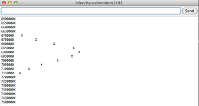
The Analog input would be plotted against frequency to show the tuned circuit's response curve.
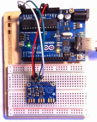
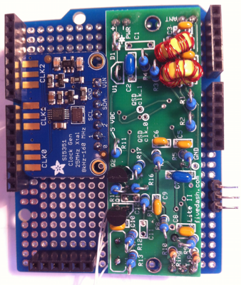
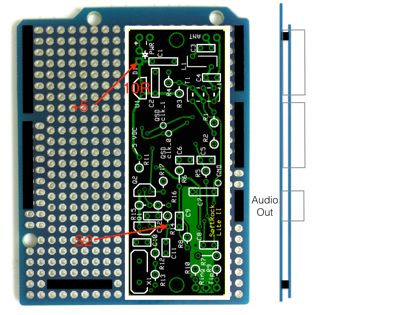
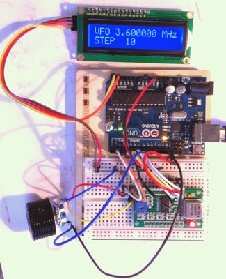
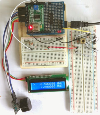
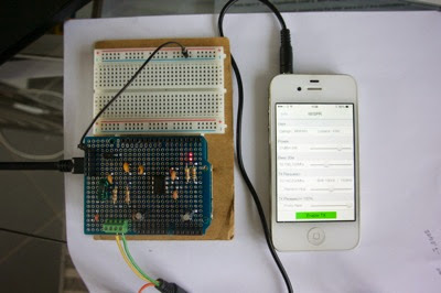
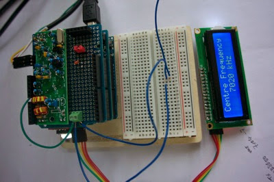
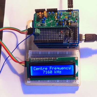
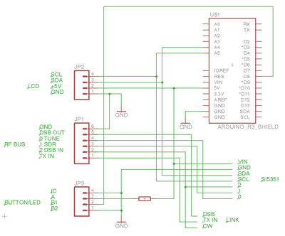
Here's the setup:

Photo 08 21 2014 14 49 37

The control is the rotary encoder. First turn it to select the start frequency, then push the button, now select the end frequency. A further push starts the scan. Like this

Photo 08 21 2014 14 43 29

Photo 08 21 2014 14 43 43

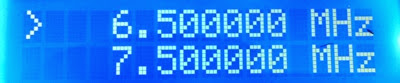
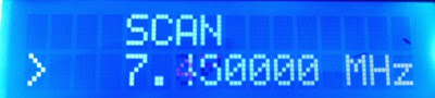
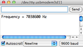
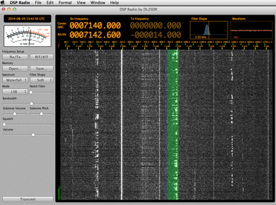
The result is shown on the Monitor, like this

Screen Shot 2014 08 21 at 14 41 59

Code

// CONNECTIONS
// A5-A0 side
// ------
// encoder KY-040
// o Grey 2 CK
// o White 3 DT
// o Blue 8 SW
// o Violet +5
// o Black GND
//
// display I2C LCD 16 * 2
// o Green A5 SCL
// o Yellow A4 SDA
// o Red GND
// o Orange +5
// ------
// D0-D13 side
//
// RF bus hardware output
// o GND
// o DSB out
// o I to SDR
// o Q to SDR
// o S0 to DSB in
// o S1 to TX (selectable S1 ad9850 or DSB out)
//
// selector output to S1: CW-S1-DSB 

#include "Encoder.h"
#include "DDS.h"
#include "Wire.h"
#include "LiquidCrystal_I2C.h"

// encoder pin connections and +5V & GND
#define CK 2
#define DT 3
#define BUTTON 8   // pin Button

// DDS pin connections
#define RST  4     // Pin  RST
#define DATA 5     // Pin  DATA
#define FQ   6     // Pin  FQ
#define CLK  7     // Pin  CLK

// input connection
#define IN A0

// I2C connections
#define SDA A4
#define SCL A5

// commands
#define SF 0 // set start freq
#define EF 1 // set end freq
#define SC 2 // scan start

// output print scale factor
#define FACTOR 2 

// Encoder object
Encoder enc(DT, CK);

// DDS object
DDS dds(CLK, FQ, DATA, RST);

// LCD object
LiquidCrystal_I2C lcd(0x27, 16, 2); 

double freq; // scan frequency
double freq1 = 6500000L; // init start & end
double freq2 = 7500000L;
long tune = 10000L; // fix button tune step and scan delta steps
long delta = 50000L;
long pos = 0; // enc positions
long newpos;
byte act = 0; // init set freq1

void setup()
{
  pinMode(BUTTON, INPUT_PULLUP); // button input

  Serial.begin(9600); // serial comms

  enc.write(0); // init encoder

  dds.init(); // init DDS
  dds.setFrequency(freq1); // set start freq

  lcd.init(); // init LCD
  lcd.backlight();
}

void loop()
{  
  byte tag;

  if(digitalRead(BUTTON) == LOW) // button pressed?
  {
    while(!digitalRead(BUTTON)); // wait for button release
    if(act == 2) act = 0; // chose actions
    else act++;
  }
  switch(act) // change delta freq
  {
  case SF: // change start freq1 in 100kHz steps
    tag = 0;
    freq1 = change(freq1);
    break;
  case EF: // change end freq2 in 100kHz steps
    tag = 1;
    freq2 = change(freq2);
    break;
  case SC: // start scan
    tag = 2;
    for(freq = freq1; freq <= freq2; freq += delta)
    { 
      delay(50);
      dds.setFrequency(freq); // output freq
      show(tag, freq1, freq); // display scan freq
      volts(freq, analogRead(IN)); // output to monitor
    }
    act = 0;
    break;
  }
  show(tag, freq1, freq2);
}

// change freq, returns new freq
long change(long f)
{
  // encoder read, updates freq
  newpos = enc.read();
  if(newpos != pos)
    f += tune * (newpos - pos) / 4; // enc gives 4 pulses per click!
  pos = newpos;
  return f;
}

// display start & end freqs in MHz
void show(byte t, double f1, double f2)
{ 
  if(t == 0) // line 1 delete ">", line 0 put ">"
  {
    lcd.setCursor(0,1);
    lcd.print(" ");
    lcd.setCursor(0,0);
    lcd.print(">");
  }
  if(t == 1) // line 0 delete ">", line 1 put ">"
  {
    lcd.setCursor(0,0);
    lcd.print(" ");
    lcd.setCursor(0,1);
    lcd.print(">");
  }

  if(t == 0 || t == 1) // line 0 f1 or "SCAN"
  {
    lcd.setCursor(4,0);
    lcd.print(f1/1000000, 6);
    lcd.setCursor(13,0);
    lcd.print("MHz");
  }
  else if(t == 2)
  {
    lcd.setCursor(4,0);
    lcd.print("SCAN         ");
  }

  lcd.setCursor(4,1);
  lcd.print(f2/1000000, 6);
  lcd.setCursor(13,1);
  lcd.print("MHz");
}

// output freq & A0 to monitor
void volts(long f, int in)
{  
  int n;

  Serial.print(f);
  n = in/FACTOR;
  while(n-- > 0)
  {
    Serial.print(" ");
  }
  Serial.println("X");
}

SDR - this is what I will do

I have struggled to build an SDR for the Arduino DDS board to tune. So I have decided to get someone else's design and mount it on an shield board.

The simple, obvious choice is the Softrock Lite ll from Tony Parks. This is a basic SDR which is what I want to build anyway, but it is debugged and ready to go. So here' what I propose.

1. Crop the schematic to accept an input from the AD9850 DDS shield I have built.

SDR schematic

2. Then plan a shield like this

SDR shield

I have ordered a kit from SDR-Kits as Fivedash are out of stock at the moment - coming soon they say...

Can't wait to see how it goes.

Wednesday 6 August 2014

WSPR - whisper

WSPR is a very low power, very slow way of transmitting some key information. It is used to test propagation conditions. You have your own WSPR transmitter, and other people will receive you. The reception data is collected on a web site and you can get an immediate map of where you are being received.

I have got a WSPR system for reception going here.

I use my browser, Safari, and connect to the web SDR receiver at websdr.ewi.utwente.nl:8901. Then I pipe the output of Safari, normally connected to the system Internal Speakers, to SoundFlower (2ch).

Screen Shot 2014 08 06 at 17 36 31

The input to the WSPR program is taken from SoundFlower (2ch) and so it receives the sound from the SDR radio.

Screen Shot 2014 08 06 at 17 35 59

This is the result.

Tuesday 5 August 2014

Arduino breadboard proto

I searched the web for ages to try to find a simple Arduino blank proto board. So many of them have added items like a reset button, LED, area to mount an SO IC chip, etc etc.

But if you want a plain proto board you can get one...

Photo 08 05 2014 11 46 16

,,. from Electan:

Screen Shot 2014 08 05 at 11 54 59

Now that is useful!

Monday 4 August 2014

LCD using I2C serial access

I have been struggling for days to try to get my LCD 1602 display, with an I2C interface board on the back, working.

To do this one needs a library called "LiquidCrystal_I2C.h" which is referenced in many places on the web. But it seems a shambles as many of the sources have modified the library code to suit a particular application and they simply don't work. I downloaded at least 5 different versions none of which worked, and my LCD just showed a line of white rectangles, nothing else.

I have now found a version of the library which works!! So if you have the same difficulty go over to the site of HobbyComponents, search for their LCD display with I2C interface, then go to the forum and there you will find a download of the library which works.

Good luck!

Saturday 2 August 2014

DDS AD9850 with encoder input and LCD display

Here's a sketch to use an AD9850 DDS with input from an encoder and output to an LCD display. This sketch will be further developed to display more parameters and to have inputs to change the scanning speed. The current one, here, increments the frequency by 10, 100, 1kHz or 10kHz per step when you press the encoder knob, not the most practical way to tune a radio.. will have to give this some thought.

Photo 08 06 2014 11 16 42

// DDS AD9850, encoder input
// display on LCD 16 * 2
// encoder A = 2, C (centre) = GND & B = 3

#include "DDS.h"
#include "Wire.h"
#include "LiquidCrystal_I2C.h"

#define ENCA 2
#define ENCB 3
// pin connections
#define RST  4     // Pin  RST
#define DATA 5     // Pin  DATA
#define FQ   6     // Pin  FQ
#define CLK  7     // Pin  CLK

#define BUTTON 8   // pin Button

// frequency change, by df
#define NC 0
#define UP 1
#define DWN 2

// I2C connections
#define SDA A4
#define SCL A5

// DDS object
DDS dds(CLK, FQ, DATA, RST);

// LCD object
LiquidCrystal_I2C lcd(0x27, 16, 2); 

double freq = 3600000L; // start freq Hz
double df = 100; // 100Hz change in frequency per click
byte chg = NC;   // flag NC = no change, UP = add df, DWN = subtract df
byte dsw = 0;    // delta freq = 10Hz

char *dtxt[4] = {
  " 10", "100", " 1K", "10K"}; // delta freq display values

void setup()
{

  pinMode(ENCA, INPUT_PULLUP); // encoder inputs
  pinMode(ENCB, INPUT_PULLUP);

  pinMode(BUTTON, INPUT_PULLUP); // button input
  
  attachInterrupt(0, doEnc, CHANGE); // interrupt on any change of pin 2

  dds.init();
  dds.setFrequency(freq);

  lcd.init();
  lcd.backlight();
  show(freq);
}

void loop()
{  
  int state;
  
  switch (chg)
  {
  case NC:
    break;
  case UP:
    freq += df;
    show(freq);
    break;
  case DWN:
    freq -= df;
    show(freq);
    break;
  }
  chg = NC;
  dds.setFrequency(freq);
  
  if(digitalRead(BUTTON) == LOW) // button pressed?
  {
    if(dsw == 3) dsw = 0;
    else dsw++;
  }
  switch(dsw)
  {
  case 0:
    df = 10;
    break;
  case 1:
    df = 100;
    break;
  case 2:
    df = 1000;
    break;
  case 3:
    df = 10000;
    break;
  }
  while(!digitalRead(BUTTON)); // wait for button release
  showd(dsw);

}

// display freq in MHz
void show(double f)
{
  lcd.setCursor(0, 0);
  lcd.print("VHF"); 

  lcd.setCursor(4, 0);
  lcd.print(f/1000000, 6);
  lcd.setCursor(13,0);
  lcd.print("MHz");
}

// display delta freq
void showd(byte d)
{
  lcd.setCursor(0, 1);
  lcd.print("STEP");
  lcd.setCursor(5,1);
  lcd.print(dtxt[d]);
}

void doEnc()
{
  if(digitalRead(ENCA) == digitalRead(ENCB))
    chg = UP;
  else
    chg = DWN;
}

DDS AD9850 Serial I/O

This is a simple sketch to use the AD9850 DDS with input from the keyboard (frequency in Hz) and display of the output frequency on the IDE Monitor.

// DDS AD9850, keyboard frequency input, use DDS library
// set Monitor for "Newline" 9600 baud

#include "DDS.h"

// pin connections
#define RST  4     // Pin  RST
#define DATA 5     // Pin  DATA
#define FQ   6     // Pin  FQ
#define CLK  7     // Pin  CLK

// DDS object
DDS dds(CLK, FQ, DATA, RST);

// start frequency
double newfreq = 7100000L; // 7.1MHz

void setup()
{

  Serial.begin(9600);
  while(!Serial);
  
  dds.init();
  dds.setFrequency(newfreq);
}

void loop()
{
  double freq;

  freq = newfreq;
  
  Serial.print("Frequency = ");
  Serial.print(freq);
  Serial.println(" Hz");

  newfreq = (double)get();

  if(newfreq != freq)
    dds.setFrequency(newfreq);
}

// get input as a float
float get()
{
  float n;

  while(Serial.available() > 0)
    Serial.read();
  while(Serial.available()  == 0) 
    n = Serial.parseFloat();
  return n;
}