I have been admiring all those LCD displays on the web showing a bar graph, but had no idea how to implement it. Until I stumbled across a French web site with a novel solution. And here it is.
This is a complete sketch in order to show the setup, but you can extract just the includes, defines and bar glyphs to use the function. The inputs to the function are the column and row at which to start the bar graph, the digital input (0 to1023 integer) and the length of the bar.
// RF_METER, voltage, dBm & Pwr if 50R load
// V2 1-3-17
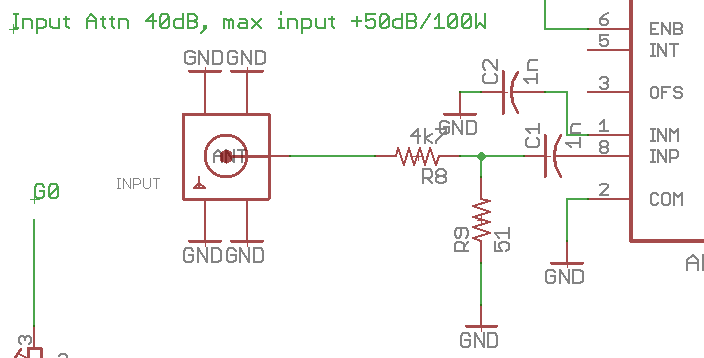
// 4k7 input impedance. 40dB attn
// LCD I2C bus (16x2)
// SDA = A4
// SCL = A5
//LCD library
#include "LiquidCrystal_I2C.h"
#include "math.h"
// chose address of 3F or 27 for LCD
//#define LCDADDR 0x27
#define LCDADDR 0x3F
#define LCDCOLS 16
#define LCDROWS 2
// Analog input pin, ref (measured) mV
// AREF can vary between Arduino, measure the 3.3V line and put AREF value here.
// scale for 80dB range to fill bar 0-1023
#define DCIN A3
#define AREF 3242.0
#define BARSCALE (1023 / 80)
// intercept (dBm), slope (mw/dB), input impedance, attenuator (dB).
// input attenuator is 4k7/51R
#define INTERCEPT -84.0
#define SLOPE 25.0
#define IMP 50.0
#define ATTN 40.0
// bar glyphs, 8 rows (top to bottom) for each glyph, 5 bits per row
uint8_t bar0[8] = {B00000, B00000, B00000, B00000, B00000, B00000, B00000, B00000};
uint8_t bar1[8] = {B00000, B10000, B10000, B10000, B10000, B10000, B00000, B00000};
uint8_t bar2[8] = {B00000, B11000, B11000, B11000, B11000, B11000, B00000, B00000};
uint8_t bar3[8] = {B00000, B11100, B11100, B11100, B11100, B11100, B00000, B00000};
uint8_t bar4[8] = {B00000, B11110, B11110, B11110, B11110, B11110, B00000, B00000};
uint8_t bar5[8] = {B00000, B11111, B11111, B11111, B11111, B11111, B00000, B00000};
// create lcd object
LiquidCrystal_I2C lcd(LCDADDR, LCDCOLS, LCDROWS);
void setup() {
Serial.begin(9600);
// init LCD
lcd.begin();
lcd.createChar(0, bar0);
lcd.createChar(1, bar1);
lcd.createChar(2, bar2);
lcd.createChar(3, bar3);
lcd.createChar(4, bar4);
lcd.createChar(5, bar5);
lcd.clear();
// 3.3V connected to AREF
analogReference(EXTERNAL);
dispMsg(0, 0, "RF"); // 0-10V bar graph goes to right...
}
void loop() {
// display dBm etc
dispDbm();
delay(100);
}
void dispDbm() {
int Ain; // int = signed 16 bit
double mW, mV, dBm, Vrms; // double = double 4 x bytes = 32bit
// calculations for mV input, dBm, mW and Volts, AREF in mV
Ain = analogRead(DCIN); // returns an int 0-1023
mV = (double)(Ain * AREF / 1023); // AREF in mV, calculate & convert to double
dBm = (mV / SLOPE) + INTERCEPT + ATTN; // in doubles
mW = pow(10.0, (dBm / 10.0)); // in double, out double
Vrms = sqrt((mW / 1000.0) * IMP); // in double, out double,
dispBar(3, 0, (dBm + 40) * BARSCALE, 13); // offset dBm and scale
lcd.setCursor(0, 1);
if (Vrms < 1.0) {
lcd.print(Vrms * 1000.0, 0);
lcd.print("mV ");
}
else {
lcd.print(Vrms, 1);
lcd.print("V ");
}
// dBm
lcd.print(dBm, 0);
lcd.print("dBm ");
// Watts
if (mW < 1000.0) {
lcd.print(mW, 0);
lcd.print("mW ");
}
else {
lcd.print(mW / 1000.0, 1);
lcd.print("W ");
}
}
// display char msg at col c, row r
void dispMsg(uint8_t c, uint8_t r, char *m)
{
lcd.setCursor(c, r);
lcd.print(m);
}
// display bar at col, row, 0-1023, length
void dispBar(uint8_t c, uint8_t r, int d, int l) {
uint8_t i, ncol;
lcd.setCursor(c, r);
ncol = map(d, 0, 1023, 0, l * 5);
for (i = 0; i < l; ++i) {
if(ncol == 0) {
lcd.write(0);
}
else if (ncol >= 5) {
lcd.write(5);
ncol -= 5;
}
else {
lcd.write(ncol);
ncol = 0;
}
}
}
}
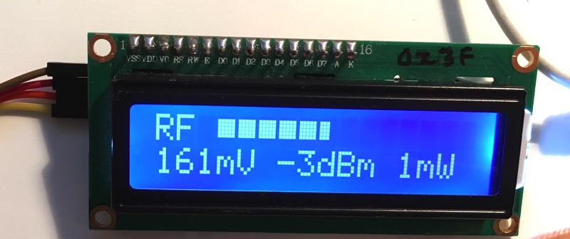
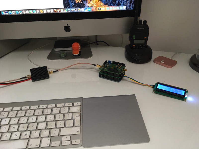
In actionAnd here is the bar graph in action on my RF METER hardware and Sketch,
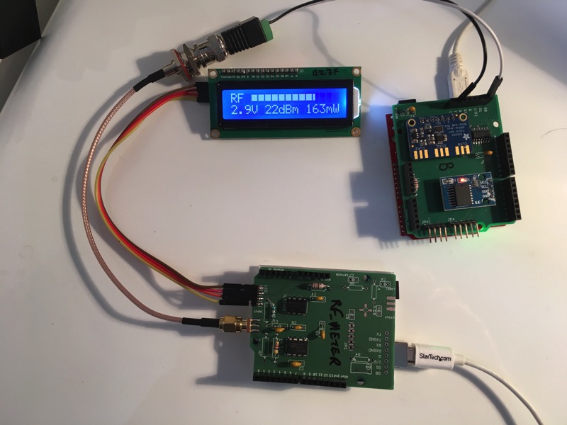
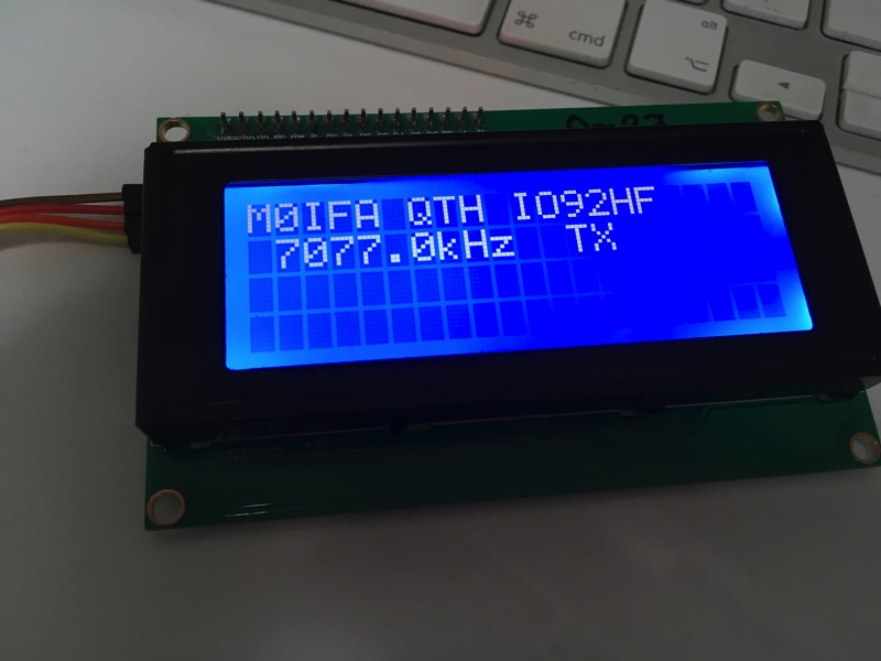
My Si5351 Digital Frequency Synthesiser is outputting RF to the RF METER board, note that here there is no 50R dummy load so its measuring voltage only, and the DDS anyway outputs square waves so it not accurate for that reason as well. When used to measure sine waves across a 50R dummy load the reading are correct.
The sketch below is using the bar graph to display the RF strength (dBm scale)
// RF_METER, voltage input sensing
// V2 1-3-17
// does not include dummy load, measures only voltage input,
// 4k7 input impedance. 40dB attn
// displays volts, watts, dBm
// LCD I2C bus (16x2)
// SDA = A4
// SCL = A5

//LCD library
#include "LiquidCrystal_I2C.h"
#include "math.h"

// chose address of 3F or 27 for LCD
//#define LCDADDR 0x27
#define LCDADDR 0x3F
#define LCDCOLS 16
#define LCDROWS 2

// Analog input pin, ref (measured) mV
// AREF can vary between Arduino, measure the 3.3V line and put AREF value here.
// scale for Vrms to fill bar (10V x 100 = 1000)
#define DCIN A3
#define AREF 3240.0
#define BARSCALE (1023 / 80)


// intercept (dBm), slope (mw/dB), input impedance, attenuator (dB).
// input attenuator is 4k7/51R
#define INTERCEPT -84.0
#define SLOPE 25.0
#define IMP 50.0
#define ATTN 40.0

// bar glyphs, 8 rows (top to bottom) for each glyph, 5 bits per row
uint8_t bar0[8] = {B00000, B00000, B00000, B00000, B00000, B00000, B00000, B00000};
uint8_t bar1[8] = {B00000, B10000, B10000, B10000, B10000, B10000, B00000, B00000};
uint8_t bar2[8] = {B00000, B11000, B11000, B11000, B11000, B11000, B00000, B00000};
uint8_t bar3[8] = {B00000, B11100, B11100, B11100, B11100, B11100, B00000, B00000};
uint8_t bar4[8] = {B00000, B11110, B11110, B11110, B11110, B11110, B00000, B00000};
uint8_t bar5[8] = {B00000, B11111, B11111, B11111, B11111, B11111, B00000, B00000};

// create lcd object
LiquidCrystal_I2C lcd(LCDADDR, LCDCOLS, LCDROWS);

void setup() {
  Serial.begin(9600);

  // init LCD
  lcd.begin();

  lcd.createChar(0, bar0);
  lcd.createChar(1, bar1);
  lcd.createChar(2, bar2);
  lcd.createChar(3, bar3);
  lcd.createChar(4, bar4);
  lcd.createChar(5, bar5);

  lcd.clear();

  // 3.3V connected to AREF
  analogReference(EXTERNAL);

  dispMsg(0, 0, "RF"); // 0-10V bar graph goes to right...
}

void loop() {
  // display dBm etc
  dispDbm();
  delay(100);
}

void dispDbm() {
  int Ain;                  // int = signed 16 bit
  double mW, mV, dBm, Vrms; // double = double 4 x bytes = 32bit


  // calculations for mV input, dBm, mW and Volts, AREF in mV
  Ain = analogRead(DCIN); // returns an int 0-1023
  mV = (double)(Ain * AREF / 1023); // AREF in mV, calculate & convert to double
  dBm = (mV / SLOPE) + INTERCEPT + ATTN; // in doubles
  mW = pow(10.0, (dBm / 10.0)); // in double, out double
  Vrms = sqrt((mW / 1000.0) * IMP); // in double, out double,

  dispBar(3, 0, (dBm + 40) * BARSCALE, 13); // BARSCALE tbd

  lcd.setCursor(0, 1);
  if (Vrms < 1.0) {
    lcd.print(Vrms * 1000.0, 0);
    lcd.print("mV ");
  }
  else {
    lcd.print(Vrms, 1);
    lcd.print("V ");
  }

  // dBm
  lcd.print(dBm, 0);
  lcd.print("dBm ");

  // Watts
  if (mW < 1000.0) {
    lcd.print(mW, 0);
    lcd.print("mW  ");
  }
  else {
    lcd.print(mW / 1000.0, 1);
    lcd.print("W   ");
  }
}

// display char msg at col c, row r
void dispMsg(uint8_t c, uint8_t r, char *m)
{
  lcd.setCursor(c, r);
  lcd.print(m);
}

// display bar at col, row, 0-1023, length
void dispBar(uint8_t c, uint8_t r, int d, int l) {
  uint8_t i, ncol;

  lcd.setCursor(c, r);

  ncol = map(d, 0, 1023, 0, l * 5);

  for (i = 0; i < l; ++i) {
    if(ncol == 0) {
      lcd.write(0);
    }
    else if (ncol >= 5) {
      lcd.write(5);
      ncol -= 5;
    }
    else {
      lcd.write(ncol);
      ncol = 0;
    }
  }
}