// GPS v3 module and LCD display
// display is limited to 16 x 2, so some data truncated
// Antony Watts 2014

/* GPS Pin connections
Module - Arduino
GND    -     GND
RX     -  Pin 11 TXPIN
TX     -  Pin 10 RXPIN
VCC    -    3.3V !!!!!
*/

// libraries
#include "SoftwareSerial.h"
#include "LiquidCrystal.h"

// GPS connections
#define RXPIN 10
#define TXPIN 11
#define BAUD 9600

// $GPRMC field positions in NMEA stream
#define RMCUTC 1
#define RMCLAT 3
#define RMCNS 4
#define RMCLON 5
#define RMCEW 6
#define RMCSOG 7
#define RMCCOG 8
#define RMCDATE 9

// LCD connections
#define RS 2
#define EN 3
#define D4 4
#define D5 5
#define D6 6
#define D7 7

// set up serial comms for GPS
SoftwareSerial gps(RXPIN, TXPIN); // serial comms to GPS UART

// Create LCD object
LiquidCrystal lcd(RS, EN, D4, D5, D6, D7);

void setup()
{
  gps.begin(BAUD); // start GPS serial
  lcd.begin(16, 2); // start LCD 16 col x 2 row
}

void loop()
{
  // main data buffers, NMEA read and field extract
  char gpsbuf[200];
  char ebuf[20];

  readgps(gpsbuf); // read each $GPxxx NMEAstrings+CRLF into gpsbuf

  // use $GPRMC string
  if(strncmp(gpsbuf, "$GPRMC", 6) == 0)
  {
    extract(RMCUTC, gpsbuf, ebuf); // get utc
    lcdrpt(ebuf, 9, 0, "**:**"); // display lcd at col 9, row 0, in format hh:mm

    extract(RMCLAT, gpsbuf, ebuf); // get lat
    lcdrpt(ebuf, 0, 1, "** ****"); // display lcd at col 0 row 1, in format dd mmmm

    extract(RMCNS, gpsbuf, ebuf); // get N|S
    lcdrpt(ebuf, 7, 1, "* ");

    extract(RMCLON, gpsbuf, ebuf); // get lon
    lcdrpt(ebuf, 9, 1, "*** **");

    extract(RMCEW, gpsbuf, ebuf); // get E|W
    lcdrpt(ebuf, 15, 1, "* ");

//    extract(RMCSOG, gpsbuf, ebuf); // get SOG

//    extract(RMCCOG, gpsbuf, ebuf); // get COG

    extract(RMCDATE, gpsbuf, ebuf); // get date
    lcdrpt(ebuf, 0, 0, "**-**-**");
  }
}

// read GPxxx NMEA string into buffer
void readgps(char *buffer)
{
  int bp;
  char c;

  bp = 0;
  do
  {
    c = gps.read();
    if(c == -1) continue; // gps sends -1 when idle
    buffer[bp++] = c;
  } while(c != '\n'); // ends with LF
  buffer[bp] = '\0'; // add '\0'
}

// extract string from field 0-10 from inbuf to outbuf
void extract(int field, char *inbuf, char *outbuf)
{
  int fcount; // field counter
  int ip; // inbuf pointer
  int op; // outbuf ptr

  fcount = 0;
  ip = 0;
  op = 0;

  while(fcount != field) // find field
  {
    while(inbuf[ip++] != ',');
    fcount++;
  }

  while(inbuf[ip] != ',') // copy inbuf to outbuf
  {
    outbuf[op++] = inbuf[ip++];
  }
  outbuf[op] = '\0'; // mark end of string
}

// display inbuf at col row in fmtbuf format
// display: * = use inbuf character, otherwise use fmtbuf character
int lcdrpt(char *inbuf, int col, int row, char *fmtbuf)
{
 int inp; // pointers to inbuf and format
 int fmtp;

 inp = 0; // start at buffers beginning
 fmtp = 0;

 lcd.setCursor(col, row);// start writing here

 while(fmtbuf[fmtp] != '\0') // continue until '\0' of format
 {
   if(fmtbuf[fmtp] == '*') // use inbuf character
   {
     lcd.write(inbuf[inp++]); // write inbuf char to lcd
   }
   else
   {
     lcd.write(fmtbuf[fmtp]); // format character
   }
   fmtp++;
 }
}
Friday 24 January 2014
GPS Version 3
Here's an update to the code:
SDR Musings
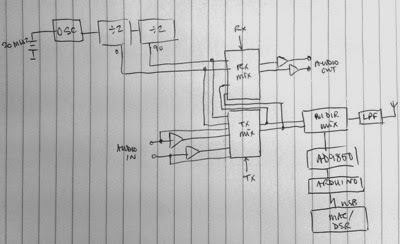
Here's a thought... for a very integrated SDR TX/RX. The idea sprung from the bi-directional mixer in the "Minima" TX/RX design plus the IQ and audio parts of the Softrock Ensemble TX/RX design. This is the idea:
Sorry for the bad photo...
The 20MHz fixed oscillator is divided by 4 to give the 0deg and 90deg phase signal for the encoder/decoder. The RX & TX mixers are the well known SDR DSB generators with audio in and out. The "Minima" balanced mixer is bi -directional (!) and interfaces on both TX & RX with the antenna through a LPF.
My guess is that this would take
1 transistor for the oscillator,
a dual JK flip flop for the diviered,
two CMOS switches for encode/decode and
a couple of FETs for the balanced mixer.
Plus a quad op amp for the audio in/out.
Pretty simple eh? and NO tuning coils or caps.
The balanced mixer is fed with I & Q signals from the local VFO/divider chain . But this could be an AD9854 synthesiser module controlled by an Arduino. The AD9854 outputs both I & Q (0 & 90deg) signals at the fundamental frequency - avoiding the need for the /4 Johnson counter. Unfortunately no one seems to make an Arduino module for the chip.
Wednesday 22 January 2014
Frequency generator AD9850
Thanks to various amateur radio enthusiasts for the code that makes this work.
I intend to expand it soon to include a tuning input (maybe push buttons, may be a knob...?) and a display of the frequency (that should be easy).
The module I used was just $3.5 on eBay!! And it is on sale from numerous suppliers in China - plus on in UK for £103!!! Clown.
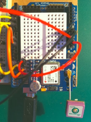
Here's the setup
It is extremely easy to use the module, just four connections if in the serial communications mode set by pulsing FQ high.
This is the code
I have so far only tested it by generating the 14.230MHz signal you can see it is programmed for and listening on an experimental SSTV receiver that I have nearly completed - more news soon.
I intend to expand it soon to include a tuning input (maybe push buttons, may be a knob...?) and a display of the frequency (that should be easy).
The module I used was just $3.5 on eBay!! And it is on sale from numerous suppliers in China - plus on in UK for £103!!! Clown.
Here's the setup
It is extremely easy to use the module, just four connections if in the serial communications mode set by pulsing FQ high.
This is the code
// DDS-9850 module programmer

#define W_CLK 8       // Pin 8  CLK
#define FQ_UD 9       // Pin 9  FQ
#define DATA 10       // Pin 10 DATA
#define RESET 11      // Pin 11 RST

#define pulseHigh(pin) {digitalWrite(pin, HIGH); digitalWrite(pin, LOW); }

void setup()
{
  pinMode(FQ_UD, OUTPUT);
  pinMode(W_CLK, OUTPUT);
  pinMode(DATA, OUTPUT);
  pinMode(RESET, OUTPUT);

  pulseHigh(RESET);
  pulseHigh(W_CLK);
  pulseHigh(FQ_UD);  // this pulse enables serial mode
}

void loop()
{
  sendFrequency(14.23e6);  // freq MHz e6
  while(1);
}

 // transfers a byte, a bit at a time, LSB first via serial DATA line
void tfr_byte(byte data)
{
  for (int i=0; i<8; i++, data>>=1)
  {
    digitalWrite(DATA, data & 0x01);
    pulseHigh(W_CLK);   //after each bit sent, CLK is pulsed high
  }
}

 // frequency calc from datasheet page 8 =  * /2^32
void sendFrequency(double frequency)
{
  int32_t freq = frequency * 4294967295/125000000;  // note 125 MHz clock on 9850

  for (int b=0; b<4; b++, freq>>=8)
  {
    tfr_byte(freq & 0xFF);
  }
  tfr_byte(0x000);   // Final control byte, all 0
  pulseHigh(FQ_UD);
}
I have so far only tested it by generating the 14.230MHz signal you can see it is programmed for and listening on an experimental SSTV receiver that I have nearly completed - more news soon.
Saturday 18 January 2014
GPS version 2
In the last post I showed my first attempt at using a GPS module and displaying the position, time and date.
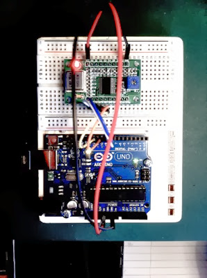
I have since updated this to use a larger screen. Here are some pictures
This is the GPS module sitting on a breadboard shield on top of an Arduino Uno.
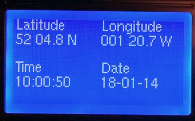
This is the display on the LCD.
To code the display I have used a library called u8glib.h available on GitHub. This is a quite complex library. It allows you to create an LCD object and defines a number of methods for acting on it.
There are a number of ways to define a "construct" (or object) but I have used this simple one for the display which is 128 x 64 with an ST7920 controller.
The Arduino pins SCK is the SPI bus clock, MOSI is the data line and SS is the chip select. These are connected to the display LCD signals E, R/W and RS.
Methods
The display can use a wide range of fonts, the one I used is called "u8g_font_helvR08" or Helvetica Regular 8 point.
Code
I have since updated this to use a larger screen. Here are some pictures
This is the GPS module sitting on a breadboard shield on top of an Arduino Uno.
This is the display on the LCD.
To code the display I have used a library called u8glib.h available on GitHub. This is a quite complex library. It allows you to create an LCD object and defines a number of methods for acting on it.
There are a number of ways to define a "construct" (or object) but I have used this simple one for the display which is 128 x 64 with an ST7920 controller.
U8GLIB_ST7920_128X64_1X lcd(SCK, MOSI, SS);
The Arduino pins SCK is the SPI bus clock, MOSI is the data line and SS is the chip select. These are connected to the display LCD signals E, R/W and RS.
Methods
lcd.begin(); // reset display and put in default state
lcd.enableCursor(); // cursor visible
lcd,disableCursor(); // cursor not visible (default state)
lcd.setCursorPos(x, y); // cursor to x, y
lcd.setColorindex(col); // BW on = 1, off = 0
lcd.drawBitMap(x, y, cnt, h, *bitmap); // draw bit map of cnt bytes
                                       // width is cnt * 8
                                       // at x, y (top left) of height h
lcd.drawBox(x, y, w, h); // filled box at x, y. width w, height h
                         // fill set by color index
lcd.drawCircle(x, y, rad, opt); // x, y centre of circle radius rad,
                                // opt is option to draw part of circle
                                // U8G_DRAW_UPPER_RIGHT, ...LEFT,
                                //  ... LOWER_LEFT, ... RIGHT, ...ALL
lcd.drawDisk(x, y, rad, opt); // as above but filled circle
lcd.drawFrame(x, y, w, h); // frame at x, y width w height h, color index
lcd.drawRFrame(x, y, w, h, r); // rounded frame, edges radius r
lcd.drawHLine(x, y, w); // draw horizontal line from x,y width w (pixels)
lcd.drawVLine(x, y, h); // draw vertical line from x, y height h (pixels)
lcd.drawLine(x1, y1, x2, y2,); // draw line from x1, y1 to x2, y2
drawTriangle(x1, y1, x2, y2, x3, y3); // filled triangle
lcd.drawPixel(x, y); // pixel at x, y
lcd.setFont(*font); // sets font - see table below
lcd.getStrWidth(*s); // returns string width in pixels in current font
lcd.drawStr(x, y, *s); // string at x, lower left of characters in setFont
                       // variations on this draw at 90, 180, 270 degrees
lcd.firstPage(); // starts a “picture loop”
lcd.nextPage(); // marks end of “picture loop”, returns 0 if finished
The display can use a wide range of fonts, the one I used is called "u8g_font_helvR08" or Helvetica Regular 8 point.
Code
#include "SoftwareSerial.h"
#include "U8glib.h"

// GPS comms 11 RX, 10 TX and LCD u8g object 6 SCK(E), 5 MOSI(RW), 4 SS(RS)
SoftwareSerial gps(10, 11);
U8GLIB_ST7920_128X64_1X u8g(6, 5, 4);

void setup()
{
    gps.begin(9600); // start GPS serial
}

void loop()
{
  char gpsbuf[200];
  char ebuf[9][20];

  readgps(gpsbuf); // read each $GPxxx NMEAstrings+CRLF into gpsbuf


  // use $GPRMC, 142759.00,A,5204.81158,N,00120.76633,W,0.107,,,090114,,,A*67
  // fields 1, 3, 4, 5, 6, 9
  if(strncmp(gpsbuf, "$GPRMC", 6) == 0)
  {
    extract(1, gpsbuf, ebuf[1]); // get utc
    fmt(ebuf[1], "**:**:**"); // format utc

    extract(3, gpsbuf, ebuf[3]); // get lat
    fmt(ebuf[3], "** ****"); // format lat

    extract(4, gpsbuf, ebuf[4]); // get N|S
    fmt(ebuf[4], "*"); // format N|S

    extract(5, gpsbuf, ebuf[5]); // get lon
    fmt(ebuf[5], "*** ****"); // format lon

    extract(6, gpsbuf, ebuf[6]); // get E|W
    fmt(ebuf[6], "*"); // format E|W

    extract(9, gpsbuf, ebuf[9]); // get date
    fmt(ebuf[9], "**-**-**"); // format date

    u8g.firstPage();
    do
    {
      u8g.setFont(u8g_font_helvR08);

      u8g.drawStr(2, 8, "Latitude");
      u8g.drawStr(66, 8, "Longitude");

      u8g.drawStr(2, 19, ebuf[3]); // Lat
      u8g.drawStr(40, 19, ebuf[4]);
      u8g.drawStr(66, 19, ebuf[5]); // Lon
      u8g.drawStr(110, 19, ebuf[6]);

      u8g.drawStr(2, 40, "Time");
      u8g.drawStr(66, 40, "Date");

      u8g.drawStr(2, 51, ebuf[1]); // UTC
      u8g.drawStr(66, 51, ebuf[9]); // Date
    } while(u8g.nextPage());
  }
}

// read GPxxx NMEA string into buffer
void readgps(char *buffer)
{
  int bp;
  char c;

  bp = 0;
  do
  {
    c = gps.read();
    if(c == -1) continue; // gps sends -1 when idle
    buffer[bp++] = c;
  } while(c != '\n'); // ends with LF
  buffer[bp] = '\0'; // add '\0'
}

// extract string from field 0-10 from inbuf to outbuf
void extract(int field, char *inbuf, char *outbuf)
{
  int fcount; // field counter
  int ip; // inbuf pointer
  int op; // outbuf ptr

  fcount = 0;
  ip = 0;
  op = 0;

  while(fcount != field) // find field
  {
    while(inbuf[ip++] != ',');
    fcount++;
  }

  while(inbuf[ip] != ',') // copy inbuf to outbuf
  {
    outbuf[op++] = inbuf[ip++];
  }
  outbuf[op] = '\0'; // mark end of string
}

// formats buffer with fmtstr, result back in buffer
void fmt(char *buffer, char *fmtstr)
{
  char tmp[20];
  int bp, fp, tp; // buffer, fmtstr & tmp pointers

  bp = 0;
  fp = 0;
  tp = 0;

  strcpy(tmp, buffer);
  while(fmtstr[fp] != '\0')
  {
    if(fmtstr[fp] == '*')
    {
      buffer[bp] = tmp[tp++];
    }
    else
    {
      buffer[bp] = fmtstr[fp];
    }
    fp++;
    bp++;
  }
  buffer[bp] = '\0';
}
Sunday 12 January 2014
GPS
Now here's a more complicated project. A GPS receiver with display of date, time, latitude and longitude. The decoded information from the receiver is:
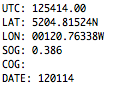
The SOG & COG are not meaningful as the receiver is not moving...
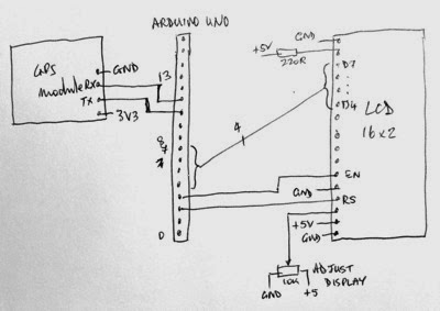
The GPS module, wiring and LCD display look like this:
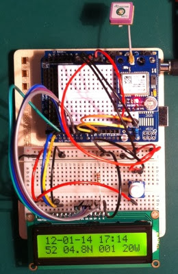
The display is limited to 16 characters so some information is truncated (no time in seconds for example, no decimal minutes of longitude). Wiring diagram:
The GPS receiver outputs various strings of information according to the NMEA specification. Noteable are these:
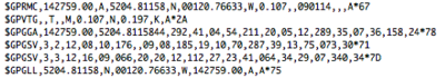
The string I am using is the $GPRMC one, which reports the data I need.
Software code
The SOG & COG are not meaningful as the receiver is not moving...
The GPS module, wiring and LCD display look like this:
The display is limited to 16 characters so some information is truncated (no time in seconds for example, no decimal minutes of longitude). Wiring diagram:
The GPS receiver outputs various strings of information according to the NMEA specification. Noteable are these:
The string I am using is the $GPRMC one, which reports the data I need.
Software code
// GPS v3 module and LCD display // display is limited to 16 x 2, so some data truncated // Antony Watts 2014 /* GPS Pin connections Module - Arduino GND - GND RX - Pin 11 TXPIN TX - Pin 10 RXPIN VCC - 3.3V !!!!! */ // libraries #include#include // GPS connections #define RXPIN 10 #define TXPIN 11 #define BAUD 9600 // $GPRMC field positions in NMEA stream #define RMCUTC 1 #define RMCLAT 3 #define RMCNS 4 #define RMCLON 5 #define RMCEW 6 #define RMCSOG 7 #define RMCCOG 8 #define RMCDATE 9 // LCD connections #define RS 2 #define EN 3 #define D4 4 #define D5 5 #define D6 6 #define D7 7 // set up serial comms for GPS SoftwareSerial gps(RXPIN, TXPIN); // serial comms to GPS UART // Create LCD object LiquidCrystal lcd(RS, EN, D4, D5, D6, D7); void setup() { gps.begin(BAUD); // start GPS serial lcd.begin(16, 2); // start LCD 16 col x 2 row } void loop() { // main data buffers, NMEA read and field extract char gpsbuf[200]; char ebuf[20]; readgps(gpsbuf); // read each $GPxxx NMEAstrings+CRLF into gpsbuf if(strncmp(gpsbuf, "$GPRMC", 6) == 0)// use $GPRMC string { extract(RMCUTC, gpsbuf, ebuf); // get utc lcdrpt(ebuf, 9, 0, "**:**"); // display lcd at col 9, row 0 extract(RMCLAT, gpsbuf, ebuf); // get lat lcdrpt(ebuf, 0, 1, "** ****"); extract(RMCNS, gpsbuf, ebuf); // get N|S lcdrpt(ebuf, 7, 1, "* "); extract(RMCLON, gpsbuf, ebuf); // get lon lcdrpt(ebuf, 9, 1, "*** **"); extract(RMCEW, gpsbuf, ebuf); // get E|W lcdrpt(ebuf, 15, 1, "* "); // extract(RMCSOG, gpsbuf, ebuf); // get SOG // extract(RMCCOG, gpsbuf, ebuf); // get COG extract(RMCDATE, gpsbuf, ebuf); // get date lcdrpt(ebuf, 0, 0, "**-**-**"); } } // read GPxxx NMEA string into buffer void readgps(char *buffer) { int bp; char c; bp = 0; do { c = gps.read(); if(c == -1) continue; // gps sends -1 when idle buffer[bp++] = c; } while(c != '\n'); // ends with LF buffer[bp] = '\0'; // add '\0' } // extract string from field 0-10 from inbuf to outbuf void extract(int field, char *inbuf, char *outbuf) { int fcount; // field counter int ip; // inbuf pointer int op; // outbug ptr fcount = 0; ip = 0; op = 0; while(fcount != field) // find field { while(inbuf[ip++] != ','); fcount++; } while(inbuf[ip] != ',') // copy inbuf to outbuf { outbuf[op++] = inbuf[ip++]; } outbuf[op] = '\0'; // mark end of string } // display inbuf at col row in fmtbuf format // display: * = use inbuf character, otherwise use fmtbuf character int lcdrpt(char *inbuf, int col, int row, char *fmtbuf) { int inp; // pointers to inbuf and format int fmtp; inp = 0; // start at buffers beginning fmtp = 0; lcd.setCursor(col, row);// start writing here while(fmtbuf[fmtp] != '\0') // continue until '\0' of format { if(fmtbuf[fmtp] == '*') // use inbuf character { lcd.write(inbuf[inp++]); // write inbuf char to lcd } else { lcd.write(fmtbuf[fmtp]); // format character } fmtp++; } }
Subscribe to:
Posts (Atom)