Thursday 11 February 2016

Simple home automation light control

I have been learning a lot in the last few days: HTML code and styles, PHP. After I set up the apache2 server on my Raspberry Pi (see previous post) I have connected four LEDs to the Pi on GPIO 22, 23, 24, & 25.

DSC 2178

HTML

Then I have written two programs. One is the "index.htm" served by apache2 from its "DocumentRoot" folder "/var/www" when you connect. This displays a series of four ON and four OFF buttons and a single ALL OFF button. The HTML code actions a PHP file when any button is pressed and passes, or POSTs, data about which button has been pressed. The code is:

Screen Shot 2016 02 11 at 13 04 27

Screen Shot 2016 02 11 at 13 04 38

In the first part some meta data is defined, this is for the iPhone which responds to the "viewport" name and sets its scaling to "1.0". This fills the screen with the HTML page. Next is a couple of style definitions for the ON and OFF "submit" buttons. The lower code shows how the form is implemented, with a style class used for ON and OFF buttons. When a typical button is clicked the action is to call the "gpio.php" file and pass the "name" with a POST method.

PHP

The "gpio.php" is

Screen Shot 2016 02 11 at 13 10 14

Here the values of the "name", e.g. "table_on" are checked to see if they are True or False. And the shell command line "exec(gpio.." is called to switch the LED on (1) or off (0).

Sunday 7 February 2016

Setting up R_PI apache2 server for Home Automation

Here's a very brief set of steps to install and set up apache2

// [add “-y” to bypass Y/n? go ahead]
sudo apt-get update
sudo apt-get upgrade
sudo apt-get install apache2 [-y]
sudo apt-get install php5 libapache2-mod-php5 [-y]

// set up permissions for /var, /var/www, /var/www/html folders
sudo addgroup www-data
sudo chown -R www-data:www-data /var
sudo adduser pi www-data

// let everyone rw www
cd /var/www/
sudo chmod 777 www
cd /var/www
sudo chmod 777 html

// delete index.html from /html
cd /var/www/html
sudo rm index.html
// remove /html
cd /var/www
sudo rm html

//restart apache
sudo service apache2 restart

// change the document root for apache2
cd /etc/apache2/sites-available/
sudo nano 000-default.conf
// change the line to "DocumentRoot /var/www" Exit ^X - "Y" and save
LIGHTS CONTROLLER

Now you are ready to put files in /var/www/. The first should be a new server index file. For the Home Automation project the index.html file is:

Screen Shot 2016 02 07 at 20 44 58

And then also in the /var/www/ folder put the gpio.php file:

Screen Shot 2016 02 07 at 20 43 54

When you point your browser at the R_IP "IP address", e.g. raspberrypi.local, you will see the index.html file

Screen Shot 2016 02 07 at 20 46 09

And when you click one of the two buttons R_PI gPIO 17 or 27 will switch ON or OFF.

What is all this HTML and PHP?

Screen Shot 2016 02 08 at 14 08 53

In the HTML file create a "form", define the action to take when this form is sent from client to server, i.e. execute "gpio.php" program on the server. Send data to the server using the method "POST" if the button "table_on" or "ON", table_off" or "OFF" are clicked. "Table Lights:" is the text to put on the form, before creating these buttons. The "submit" creates the button with a value written on it of "ON". (the second "input" creates a second button "OFF"). Pressing the button sends a value of "True" only when a button is pressed.

Screen Shot 2016 02 08 at 14 14 57

In the PHP file, the variable "$_POST['table_on']" is tested by "isset(...) function to see if it is set "True" becaue this button was pressed. If so it executes the command in "exec(...);"

Thursday 4 February 2016

Researching Home Automation for Raspberry Pi

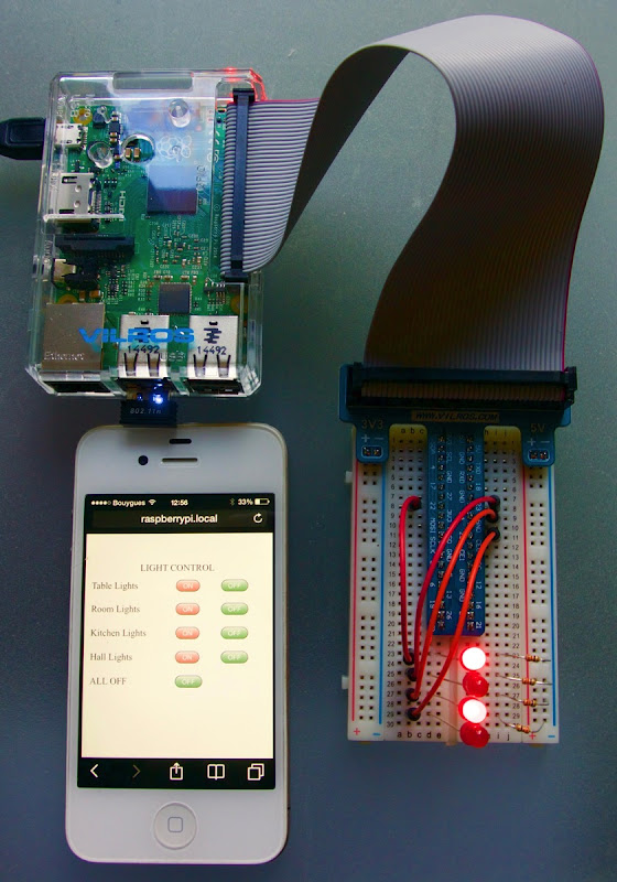
I think I have found the first half of the solution for home automation using the R_PI. This first step is to just turn on/off some AC outlets. This step connects the R_PI to the AC outlet sockets. The second step will be to have a WiFi iPhone to R_PI connection to remotely control the sockets.

Energenie

A company called Energenie has a system of plugs that work using a 400MHz Tx/Rx system. And what is wonderful, they have made an interface for the R_PI, a small plugin board that is a Tx/Rx and connects to the R_PI GPIOs. This allows a Python program driving the GPIOs with the correct codes to turn the sockets on and off.They also provide a Python Library for the system implementation. Up to 4 sockets can be controlled.

Screen Shot 2016 02 04 at 15 04 50

They provide a sample Python program to demonstrate the system working. Here it demos the codes:

#import the required modules
import RPi.GPIO as GPIO
import time

# set the pins numbering mode
GPIO.setmode(GPIO.BOARD)

# Select the GPIO pins used for the encoder K0-K3 data inputs
GPIO.setup(11, GPIO.OUT)
GPIO.setup(15, GPIO.OUT)
GPIO.setup(16, GPIO.OUT)
GPIO.setup(13, GPIO.OUT)

# Select the signal to select ASK/FSK
GPIO.setup(18, GPIO.OUT)

# Select the signal used to enable/disable the modulator
GPIO.setup(22, GPIO.OUT)

# Disable the modulator by setting CE pin lo
GPIO.output (22, False)

# Set the modulator to ASK for On Off Keying
# by setting MODSEL pin lo
GPIO.output (18, False)

# Initialise K0-K3 inputs of the encoder to 0000
GPIO.output (11, False)
GPIO.output (15, False)
GPIO.output (16, False)
GPIO.output (13, False)

# The On/Off code pairs correspond to the hand controller codes.
# True = '1', False ='0

print ("OUT OF THE BOX: Plug the Pi Transmitter board into the Raspberry Pi")
print ("GPIO pin-header ensuring correct polarity and pin alignment.")
print ("")
print ("The sockets will need to be inserted into separate mains wall sockets.")
print ("with a physical separation of at least 2 metres to ensure they don't")
print ("interfere with each other. Do not put into a single extension lead.")
print ("")
print ("For proper set up the sockets should be in their factory state with")
print ("the red led flashing at 1 second intervals. If this is not the case for")
print ("either socket, press and hold the green button on the front of the unit")
print ("for 5 seconds or more until the red light flashes slowly.")
print ("")
print ("A socket in learning mode will be listening for a control code to be")
print ("sent from a transmitter. A socket can pair with up to 2 transmitters")
print ("and will accept the following code pairs")
print ("")
print ("0011 and 1011 all sockets ON and OFF")
print ("1111 and 0111 socket 1 ON and OFF")
print ("1110 and 0110 socket 2 ON and OFF")
print ("1101 and 0101 socket 3 ON and OFF")
print ("1100 and 0100 socket 4 ON and OFF")
print ("")
print ("A socket in learning mode should accept the first code it receives")
print ("If you wish the sockets to react to different codes, plug in and")
print ("program first one socket then the other using this program.")
print ("")
print ("When the code is accepted you will see the red lamp on the socket")
print ("flash quickly then extinguish")
print ("")
print ("The program will now loop around sending codes as follows when you")
print ("hit a key:")
print ("socket 1 on")
print ("socket 1 off")
print ("socket 2 on")
print ("socket 2 off")
print ("all sockets on")
print ("all sockets off")
print ("Hit CTL C for a clean exit")

try:
	# We will just loop round switching the units on and off
	while True:
		input('hit return key to send socket 1 ON code')
		# Set K0-K3
		print ("sending code 1111 socket 1 on")
		GPIO.output (11, True)
		GPIO.output (15, True)
		GPIO.output (16, True)
		GPIO.output (13, True)
		# let it settle, encoder requires this
		time.sleep(0.1)
		# Enable the modulator
		GPIO.output (22, True)
		# keep enabled for a period
		time.sleep(0.25)
		# Disable the modulator
		GPIO.output (22, False)

		input('hit return key to send socket 1 OFF code')
		# Set K0-K3
		print ("sending code 0111 Socket 1 off")
		GPIO.output (11, True)
		GPIO.output (15, True)
		GPIO.output (16, True)
		GPIO.output (13, False)
		# let it settle, encoder requires this
		time.sleep(0.1)
		# Enable the modulator
		GPIO.output (22, True)
		# keep enabled for a period
		time.sleep(0.25)
		# Disable the modulator
		GPIO.output (22, False)

		input('hit return key to send socket 2 ON code')
		# Set K0-K3
		print ("sending code 1110 socket 2 on")
		GPIO.output (11, False)
		GPIO.output (15, True)
		GPIO.output (16, True)
		GPIO.output (13, True)
		# let it settle, encoder requires this
		time.sleep(0.1)
		# Enable the modulator
		GPIO.output (22, True)
		# keep enabled for a period
		time.sleep(0.25)
		# Disable the modulator
		GPIO.output (22, False)

		input('hit return key to send socket 2 OFF code')
		# Set K0-K3
		print ("sending code 0110 socket 2 off")
		GPIO.output (11, False)
		GPIO.output (15, True)
		GPIO.output (16, True)
		GPIO.output (13, False)
		# let it settle, encoder requires this
		time.sleep(0.1)
		# Enable the modulator
		GPIO.output (22, True)
		# keep enabled for a period
		time.sleep(0.25)
		# Disable the modulator
		GPIO.output (22, False)

		input('hit return key to send ALL ON code')
		# Set K0-K3
		print ("sending code 1011 ALL on")
		GPIO.output (11, True)
		GPIO.output (15, True)
		GPIO.output (16, False)
		GPIO.output (13, True)
		# let it settle, encoder requires this
		time.sleep(0.1)
		# Enable the modulator
		GPIO.output (22, True)
		# keep enabled for a period
		time.sleep(0.25)
		# Disable the modulator
		GPIO.output (22, False)

		input('hit return key to send ALL OFF code')
		# Set K0-K3
		print ("sending code 0011 All off")
		GPIO.output (11, True)
		GPIO.output (15, True)
		GPIO.output (16, False)
		GPIO.output (13, False)
		# let it settle, encoder requires this
		time.sleep(0.1)
		# Enable the modulator
		GPIO.output (22, True)
		# keep enabled for a period
		time.sleep(0.25)
		# Disable the modulator
		GPIO.output (22, False)

# ^C clean up the GPIOs for next time
except KeyboardInterrupt:
	GPIO.cleanup()
But using their Library "energenie" this can be simplified:
from energenie import switch_on, switch_off
from time import sleep

# turn all plug sockets on and off
switch_on()
switch_off()

# turn a plug socket on and off by number
switch_on(1)
switch_off(1)

switch_on(3)
switch_off(3)

# turn some plug sockets on, then turn them off after 10 seconds
switch_on(1)
switch_on(4)
sleep(10)
switch_off(1)
switch_off(4)
That's pure genius I think!

Tuesday 2 February 2016

Learning about Python and R_PI

I decided to try one of the learn modules on the Raspberry Pi web site. This introduces me to

1 Python3

2 Using the GPIO pins

I wired up the 10 LEDs as shown on the R_PI project page. Then started Menu > Programming > Python 3. The first window is raw access to the Python interpreter, here you can type commands and see them happen. To create an app you need to open File > New File in a new window, here you can type your program. You must save it, so I suggest to go out to the File Manager and create a new folder under Documents > Python3 Projects. Then you can save you work there.

The program looks like this:

import requests
from gpiozero import LED

pins = [2, 3, 4, 14, 15, 17, 18, 27, 23, 22]
leds = [LED(p) for p in pins]

url = "http://api.open-notify.org/astros.json"

r = requests.get(url)
j = r.json()
n = j['number']

for i, led in enumerate(leds):
    if n > i:
        led.on()
    else:
        led.off()
I saved it as astros.py. Run it by Run > Run Module. And if you got it all wired up right and typed in right, at this moment there are 6 astronauts on the ISS so 6 LEDs will light up.

As I understand it the program works like this

- import the libraries you need "requests" and the "gpiozero" function "LED".

- define a list of the led pins you have wired up

- make another list from this of the leds you will access and their pin numbers

- define the url for the data and get the data from it into variable "r"

- read the json data into the variable "j"

- finally extract the 'number' of astronauts from the json "number" data

- enumerate the leds - simply number them 0...9. And step through them in a "for" loop. If the number of astronauts "n" is more than the current led "i" in the loop, turn it on. Else turn it off.

This will give 6 LEDs on for 6 astronauts.

Raspberry Pi CRASH - start again

A few weeks ago I bought a Raspberry Pi, I thought I would play with it. It was a kit from VILROS. I added to it a very small USB/Dongle keyboard. I set it up by connecting the HDMI output to my TV, plugged in the KB dongle and inserted the supplied SD Card (they said it was the latest version of NOOBS/Raspian OS!!!). I started up and the installation went well.

Then I started to try to learn about the R_PI... and Raspian/Debian/Linux/Unix, oh my goodness, how many nerds are there in the world? There is site after site on the web all giving conflicting advice about how to do this and that. In the end I loaded a few extra bits of software (for Bonjour, VNC access). I also tried Javascript. In the end my Python, C and Javascript programs have crashed. The programs do not run. They ran once, but now something has happened. All I get is inscrutable error messages. I stand no chance at all of finding the solution.

Turns out the SD card supplied was NOT the latest NOOBS/Raspian OS and was missing a lot of stuff. Lucky it worked at all really. Message to all out there: buy a blank SD Card, download the latest NOOBS from the Raspberry Pi web site and install it yourself. Then do an update and upgrade to get a clean new system.

I am starting again... follow along if you like

These instructions are what I did on my iMac, a PC may be different...

1 Find and Install SDFormatter program on your iMac / PC

2 Download NOOBS. I used the zip version (1.1GB)

3 Format the SD Card, chose "Overwrite Format", name it "NOOBS". Mine is a 7.97GB card. Format takes a while...

4 Unzip downloaded NOOBS_v1_x_x_x.zip

5 Copy all files in the folder to the SD Card using the Mac Finder, Eject the card

6 Put the SD Card into the R_PI. Connect HDMI (a TV), Insert USB KB dongle, switch on KB. Power up the R_PI. Wait for all the startup garbage to pass by on the screen...

7 Select "Raspian" OS and Install (3.1GB). Takes a while...

8 Starts up at R_PI Desktop.

9 Open LXTerm and Find the R_PI IP address

	ifconf			# find pi_ip_addr (wlan)
	sudo raspi-config	# chose command line auto-startup, reboot
Then connect by
	ssh pi@pi_ip_addr 	# connect from Mac Terminal
Which makes it easier to
	sudo apt-get update 	# of apps listed in /etc/apt/sources.list
	sudo apt-get upgrade	# upgrade all apps
	sudo apt-get dist-upgrade	# upgrade OS
	sudo apt-get autoremove	# remove unused apps
... and wait very patiently for it to upgrade.

10 Now get Bonjour working (to access R_PI as "raspberrypi.local" on your WiFi) and VNC working (to view the Desktop on your Mac/PC screen - use VNC Viewer software). There is a very good system called "netatalk" for Macs which not only allows you to login to the R_PI from the Terminal app using ssh, but also places the "raspberrypi" in the Mac Finder's sidebar so you can copy files to/from it. Install these two and then start the VNC server:
	sudo apt-get install avahi-daemon # included in netatalk?
	sudo apt-get install netatalk	 # add AFP protocol
	sudo apt-get install tightvncserver
	tightvncserver	 # and create a VNC login password
Now access the R_PI from your Mac Terminal, give the password "raspberry"
	ssh pi@raspberrypi.local
	password: raspberry
Screen Shot 2016 03 05 at 19 36 08

and use VNC by starting a VNC server channel on the R_PI command line, first launch the server, screen "0"
pi@raspberrypi:~ $ vcnserver :0
second, start the VNC Viewer program on your Mac and connect to raspberrypi.local. Create your own password.

Screen Shot 2016 03 05 at 19 36 20

After all that

I am back to ground zero and have to start my app writing efforts all over again. Wouldn't it be nice to have a solid, stable computer to do it on. Maybe this version of NOOBS/Raspian will be better...