Thursday 21 May 2015

WSPR with RTC timing

Transmitting WSPR has to be done exactly on time. It means a sequence of symbols has to start on an even minute, within the first second! How to do this?

There are four possible ways as far as I can see, get time from your computer if you are using a computer program and you have accurately set your computer's time; get time from a GPS receiver or a DFC77 receiver or a Real Time Clock chip which has been set correctly.

RTC solution

So far I have looked at only the RTC solution using an IC the DS1307, one of the simplest RTCs, but not one of the most accurate.

DS1307

This is a module from Adafruit:

Screen Shot 2015 05 21 at 11 00 12

It has the DS1307 IC, a couple of I2C bus pull-up resistors, the XTAL at 32768Hz and a back-up battery to maintain the circuit in operation when the +5V supply is off. The connections are

GND - ground

5V - +5V supply

SDA & SCL - the I2C bus

SQW - a pulse output which can be programmed to be 1Hz, 4.096kHz, 8.192kHz or 32.768kHz, HIGH or LOW output

Software

There seems to be a multitude of libraries for the RTC on the web, notably RTClib from Adafruit. But I believe most are not necessary to read the time from the chip as its operation is quite simple. For setting the time there is a clever program from Adafruit to set the initial time - see their web site. This only need be run once, or as frequently as your clock needs calibrating, it transfers your computer time to the DS1307).

DS1307 registers

The DS1307 has its main I2C address at 0x68h, this allows you to address 7 registers. The time is available in these registers in BCD (binary coded decimal) format (e.g. 15 = 0001 1001).

0x00	Seconds, b7 = 1 is halt oscillator, so mask this if writing time to the IC
0x01	Minutes
0x02	Hours, b6 = HIGH = 12, LOW = 24. In 12 mode, b6 reads AM = LOW/PM = HIGH
0x04	Date
0x05	Month
0x06 	Year


A further register can be addressed at 0x07h, this is a control register like this

b0	RS0 set freq output on SQWE
b1	RS1 “ - “
b2&3	-
b4	SQWE/OUT, square wave SQW enable, set SQWE = HIGH
b5&6	-
b7	OUT output level of pin OUT = 1, HIGH, out = 0 LOW

	RS0		RS1		SQWE
	0		0		1Hz
	0		1		4kHz (4096Hz)
	1		0		8kHz (8092Hz)
	1		1		32kHz (32768Hz)

This control register is set to 0x00h (0000 0000b) on power up, it should not need to be set for normal use.

Here is a small example of how to read the time, and convert it from BCD to decimal and display it on an LCD.

Code

#include "Wire.h"
#include "RTClib.h"
#include "LiquidCrystal_I2C.h"

// LCD
#define LCDADDR 0x27
#define LCDCOLS 16
#define LCDROWS 2

#define RTCADDR 0x68

// LCD object
LiquidCrystal_I2C lcd(LCDADDR, LCDCOLS, LCDROWS);

RTC_DS1307 rtc;

byte sec, mts, hr, wkday, mthday, mth, yr;

void setup()
{
  // init LCD & backlight on
  lcd.init();
  lcd.backlight();

  // init time from computer
  rtc.adjust(DateTime(__DATE__, __TIME__));
}

void loop() {
  // read registers and load bytes with time
  getTime();
  dispTime(4, 1);
}

void getTime() {
  // Reset the register pointer
  Wire.beginTransmission(RTCADDR);
  byte zero = 0x00;
  Wire.write(zero);
  Wire.endTransmission();
  
  // request 7 bytes from the RTC address
  Wire.requestFrom(RTCADDR, 7);

  // get the time data
  sec = bcdToDec(Wire.read());
  mts = bcdToDec(Wire.read());
  hr = bcdToDec(Wire.read() & 0b111111); //24 hour time
  wkday= bcdToDec(Wire.read()); //0-6 -> Sunday - Saturday
  mthday = bcdToDec(Wire.read());
  mth = bcdToDec(Wire.read());
  yr = bcdToDec(Wire.read());
}

// Convert binary coded decimal to normal decimal numbers
byte bcdToDec(byte val) {
  return ( (val/16*10) + (val%16) );
}

// display time at col, row
void dispTime(byte c, byte r) {
  lcd.setCursor(c, r);
  if(hr < 10)
    lcd.print("0");
  lcd.print(hr);
  lcd.print(":");
  if(mts < 10)
    lcd.print("0");
  lcd.print(mts);
  lcd.print(":");
  if(sec < 10)
    lcd.print("0");
  lcd.print(sec);
}


The main steps are to reset the internal address pointer to point to the first register (reg0), then to sequentially read the registers to get the data, and convert it to decimal.

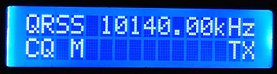
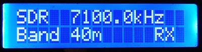
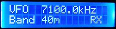
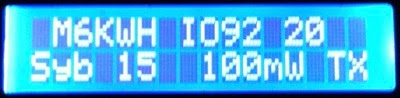
Following this idea I think that this code would work to trigger a WSPR transmission at an even minute.

Code

// Universal_WSPR_RTC transmits WSPR
// use WSPR_Symbol_Generator sketch to make symbol tone table
// here it is hard coded for msgtxt " M6KWH IO92 20", note leading space, 3rd char must be number
// insert symbols and msgtxt below
// step in 50Hz steps, giving 5 frequencies per band
// output on CLK0, Universal VFO shield "VFO" pin
// Interface by I2C bus to RTC DS1307
// DS1307 must be intitialised with time before use, button selects repeat time 2, 4, 6, 8 min

// CONNECTIONS
// RTC DS1307
// SCL = A5
// SDA = A4
// I2C address 0x68
// -----
// DDS I2C SI5351
// SCL = A5
// SDA = A4
// I2C address 0x60
// ------
// display I2C LCD 16 * 2
// o A5 SCL (y)
// o A4 SDA (or)
// o +5     (r)
// o GND    (bwn)
// I2C address 0x27
// -----
// encoder KY-040
// o D2 DT  (y)
// o D3 CLK (g)
// o D4 SW  (or)
// o +5     (r)
// o GND    (bwn)
// -----

// libraries
#include "Wire.h"
#include "si5351.h"
#include "LiquidCrystal_I2C.h"
#include "Rotary.h"
#include "TimerOne.h"

// RTC I2C address
#define RTCADDR 0x68

// LCD
#define LCDADDR 0x27
#define LCDCOLS 16
#define LCDROWS 2

// rotary Encoder pins 2 & 3 (DT & CLK), button 4 (SW)
#define DT 2
#define CLK 3
#define SW 4

// receive & transmit enable output pins
#define RX 13
#define TX 12

// dds object
Si5351 dds;

// LCD object
LiquidCrystal_I2C lcd(LCDADDR, LCDCOLS, LCDROWS);

// rotary sncoder object
Rotary rot = Rotary(DT, CLK);

uint32_t freq;
uint8_t tone_ptr = 0; // Pointer to the current symbol
volatile uint8_t next_tone = 0; // Incremented by the ISR
uint8_t next_tone2 = 0; // Local store, to compare against.
uint8_t step_tone = 0; // Flag used to signify we need to move to the next symbol
uint8_t b; // band 0 - 26

// band frequencies (cHz)
uint32_t band[15] =
{ 704000000, 704005000, 704010000, 704015000, 704020000,
  1014010000, 1014015000, 1014020000, 1014025000, 1014030000,
  1409700000, 1409705000, 1409710000, 1409715000, 1409720000
}; // 40, 30, 20m

// ====================== insert your message text & symbol
char msgtxt[] = {" M6KWH IO92 20  "};
// insert symbols - use WSSPR Symbol Generator program to create
uint8_t msg[162] =
{ 3, 1, 2, 0, 0, 0, 2, 2, 1, 2, 0, 2, 3, 1, 3, 0, 2, 2, 1, 2, 0, 3, 0, 1, 3, 1, 1, 0, 2, 0, 0, 2,
  0, 0, 1, 0, 0, 1, 0, 1, 2, 0, 0, 0, 0, 2, 1, 2, 1, 3, 0, 0, 1, 3, 0, 1, 2, 0, 0, 1, 3, 2, 1, 0,
  2, 2, 0, 3, 3, 2, 3, 2, 3, 0, 3, 0, 3, 2, 0, 3, 2, 0, 1, 2, 1, 3, 0, 0, 0, 3, 1, 0, 1, 0, 1, 0,
  2, 2, 3, 0, 0, 0, 0, 0, 1, 0, 2, 1, 0, 2, 1, 3, 1, 2, 1, 1, 0, 0, 3, 3, 2, 1, 2, 0, 0, 1, 1, 1,
  2, 2, 2, 0, 0, 3, 0, 3, 2, 0, 3, 1, 2, 2, 2, 0, 2, 0, 2, 3, 1, 0, 1, 0, 1, 1, 2, 0, 0, 3, 1, 0,
  2, 0
};
// ======================

// tone out at tuned freq + tone (cHz above)
uint32_t tones[4] = {0, 146, 293, 440};

// RTC time sec & mins, sec = 1 means no WSPR TX, yr = 0 means RTC not running
byte sec, mns, hr;

// repeat frequency
uint8_t repeat;

void setup()
{
  // initialise the wire library for I2C comms
  Wire.begin();

  // init LCD & backlight on
  lcd.init();
  lcd.backlight();

  // init dds
  dds.init(SI5351_CRYSTAL_LOAD_8PF, 0); // default 25MHz XTAL

  // all CLK disabled
  dds.output_enable(SI5351_CLK0, 0);
  dds.output_enable(SI5351_CLK1, 0);
  dds.output_enable(SI5351_CLK2, 0);

  // encoder, button, RX & TX pins
  pinMode(DT, INPUT_PULLUP);
  pinMode(CLK, INPUT_PULLUP);
  pinMode(SW, INPUT_PULLUP);
  pinMode(RX, OUTPUT);
  pinMode(TX, OUTPUT);

  digitalWrite(RX, LOW); // RX
  digitalWrite(TX, HIGH); // no TX

  b = 7; // band, middle 30m
  repeat = 2; // init to send every 2 mins

  dispMsg(0, 0, "WSPR            ");
  dispFreq(5, 0, band[b], 2); // display freq b
  dispMsg(1, 1, " min");
  dispNum(0, 1, repeat);
}

void loop()
{
  tune(); // tune freq?
  event(); // set repeat timing 2,4,6,8 min?

  getRTC(); // read RTC, display time

  // send WSPR now?
  if (mns % repeat == 0 && sec == 0)
  {
    // display message
    dispMsg(0, 0, msgtxt);
    dispMsg(0, 1, " Symbol       TX"); // show symbol number & transmit

    txWspr(b); // transmit on freq b

    // restore display
    dispMsg(0, 0, "WSPR           ");
    dispFreq(5, 0, band[b], 2); // display freq
    dispMsg(1, 1, " min");
    dispNum(0, 1, repeat);
  }
}

void tune()
{
  unsigned char dir; // tuning direction CW/CCW

  dir = rot.process(); // read encoder
  if (dir != DIR_NONE) // turned?
  {
    if (dir == DIR_CW && b > 0) b += 1; // increment band freq +/- 1
    if (dir == DIR_CCW && b < 15) b -= 1;

    dispFreq(5, 0, band[b], 2); // display freq
  }
}

// set event time 4,6,8,10 min
void event()
{
  if (digitalRead(SW) == LOW)
  {
    while (!digitalRead(SW)); // wait for release
    if (repeat == 8) repeat = 2;
    else repeat += 2;
    dispMsg(1, 1, " min");
    dispNum(0, 1, repeat);
  }
}

// transmit msg at freq fTable[b]
void txWspr(uint8_t b)
{
  // Start Transmitter
  digitalWrite(RX, HIGH);
  digitalWrite(TX, LOW);

  // Start the timer interrupt, is called every 8192/12000 seconds.
  Timer1.initialize(682666UL);
  Timer1.attachInterrupt(wspr_isr);

  // Transmit!
  while (1)
  {
    // do the increment checking without the interrupts, in case it gets
    // modified while we are checking.
    noInterrupts();
    if (next_tone > next_tone2)
    {
      step_tone = 1;  // next_tone has incremented, raise flag
      next_tone2 = next_tone;
    }
    interrupts();

    if (step_tone)
    {
      // Got a call from the ISR to increment the tone, reset flag
      step_tone = 0;

      // We enable the clock here to avoid having it be active before the first tone
      // is due to be transmitted.
      dds.output_enable(SI5351_CLK0, 1);

      // output freq
      freq = band[b] + tones[msg[tone_ptr]];
      freqOut(freq);

      dispNum(8, 1, tone_ptr); // display tone number
      tone_ptr++; // next tone

      // If we're at the end of the symbol array, disable the timer and break.
      if (tone_ptr == 162)
      {
        Timer1.detachInterrupt();
        next_tone = 0;
        next_tone2 = 0;
        tone_ptr = 0;
        break;
      }
    }
  }

  // Disable clock, stop Tx
  dds.output_enable(SI5351_CLK0, 0);
  digitalWrite(TX, HIGH);
  digitalWrite(RX, LOW);
}

// Timer ISR.
void wspr_isr(void)
{
  next_tone += 1;
}

// frequency (in cHz) for VFO, on CLK0
void freqOut(uint32_t f)
{
  dds.set_freq(f, 0ULL, SI5351_CLK0); // f cHz
}

// get time from RTC, convert bcd to decimal
void getRTC()
{
  // Reset the register pointer
  Wire.beginTransmission(RTCADDR);
  byte zero = 0x00;
  Wire.write(zero);
  Wire.endTransmission();

  // request 1st 7 bytes from the RTC address
  Wire.requestFrom(RTCADDR, 3);

  // get the s/m/h time data
  sec = bcdToDec(Wire.read());
  mns = bcdToDec(Wire.read());
  hr = bcdToDec(Wire.read() & 0b111111); //24 hour time
  dispTime(8, 1);
}

// Convert binary coded decimal to normal decimal numbers
byte bcdToDec(byte val)
{
  return ( (val / 16 * 10) + (val % 16) );
}

// display char msg at col c, row r
void dispMsg(uint8_t c, uint8_t r, char *m)
{
  lcd.setCursor(c, r);
  lcd.print(m);
}

// display a number at col c, row r
void dispNum(uint8_t c, uint8_t r, uint16_t n)
{
  lcd.setCursor(c, r);
  lcd.print(n);
}

// display freq in kHz,col c, row r, d decimal places
void dispFreq(uint8_t c, uint8_t r, uint32_t f, uint8_t d)
{
  lcd.setCursor(c, r); // clear last freq display
  lcd.print((float)f / 100000, d); // convert to float for print function

  lcd.print("kHz  "); // + trailing spaces to clear previous display
}

// display time at col, row
void dispTime(byte c, byte r) {
  lcd.setCursor(c, r);
  if(hr < 10)
    lcd.print("0");
  lcd.print(hr);
  lcd.print(":");
  if(mns < 10)
    lcd.print("0");
  lcd.print(mns);
  lcd.print(":");
  if(sec < 10)
    lcd.print("0");
  lcd.print(sec);
}


I have not verified this actually transmits yet, when I build the Concept stack (RTC + VFO) I will let you know

Sunday 17 May 2015

Universal HELL sketch (Hellschrieber)

Here is the code to build a Hellschreiber transmitter. The button changes the band, the encoder tunes in 10Hz steps and a message is sent when entered on the Arduino IDE monitor. The basis of this code was found on the internet, so I am not so clever as all that!

Photo 05 17 2015 22 07 25

Photo 05 17 2015 22 08 14

Code

// Universal_VFO_HELL outputs Hellschrieber message
// keys LP PA or 403020 PA on pin D12, VFO runs continuously

// ----- SHIELD CONNECTIONS
// DDS I2C SI5351
// SCL = A5
// SDA = A4
// I2C address 0x60
// ------
// display I2C LCD 16 * 2
// o A5 SCL (y)
// o A4 SDA (or)
// o +5     (r)
// o GND    (bwn)
// I2C address 0x27
// -----
// encoder KY-040
// o D2 DT  (y)
// o D3 CLK (g)
// o +5     (r)
// o GND    (bwn)

// I2C, Si5351 libraries
#include "Wire.h"
#include "si5351.h"
#include "LiquidCrystal_I2C.h"
#include "Rotary.h"

// LCD
#define LCDADDR 0x27
#define LCDCOLS 16
#define LCDROWS 2

// rotary Encoder pins 2 & 3 (DT & CLK)
#define DT 2
#define CLK 3
#define SW 4

// RX & TX enable
#define RX 13
#define TX 12

#define MSGSIZE 30

// dds object
Si5351 dds;

// LCD object
LiquidCrystal_I2C lcd(LCDADDR, LCDCOLS, LCDROWS);

// rotary Encoder object
Rotary rot = Rotary(DT, CLK);

// message, new data in flag
char msg[MSGSIZE];
bool newMsg = false;

// band
byte band;

// freq
uint32_t freq;
uint32_t startFreq[] = {707700000, 1014400000, 1406000000};


typedef struct glyph {
  char ch ;
  word col[7] ;
} Glyph ;

const Glyph glyphtab[] PROGMEM = {
  {' ', {0x0000, 0x0000, 0x0000, 0x0000, 0x0000, 0x0000, 0x0000}},
  {'A', {0x07fc, 0x0e60, 0x0c60, 0x0e60, 0x07fc, 0x0000, 0x0000}},
  {'B', {0x0c0c, 0x0ffc, 0x0ccc, 0x0ccc, 0x0738, 0x0000, 0x0000}},
  {'C', {0x0ffc, 0x0c0c, 0x0c0c, 0x0c0c, 0x0c0c, 0x0000, 0x0000}},
  {'D', {0x0c0c, 0x0ffc, 0x0c0c, 0x0c0c, 0x07f8, 0x0000, 0x0000}},
  {'E', {0x0ffc, 0x0ccc, 0x0ccc, 0x0c0c, 0x0c0c, 0x0000, 0x0000}},
  {'F', {0x0ffc, 0x0cc0, 0x0cc0, 0x0c00, 0x0c00, 0x0000, 0x0000}},
  {'G', {0x0ffc, 0x0c0c, 0x0c0c, 0x0ccc, 0x0cfc, 0x0000, 0x0000}},
  {'H', {0x0ffc, 0x00c0, 0x00c0, 0x00c0, 0x0ffc, 0x0000, 0x0000}},
  {'I', {0x0ffc, 0x0000, 0x0000, 0x0000, 0x0000, 0x0000, 0x0000}},
  {'J', {0x003c, 0x000c, 0x000c, 0x000c, 0x0ffc, 0x0000, 0x0000}},
  {'K', {0x0ffc, 0x00c0, 0x00e0, 0x0330, 0x0e1c, 0x0000, 0x0000}},
  {'L', {0x0ffc, 0x000c, 0x000c, 0x000c, 0x000c, 0x0000, 0x0000}},
  {'M', {0x0ffc, 0x0600, 0x0300, 0x0600, 0x0ffc, 0x0000, 0x0000}},
  {'N', {0x0ffc, 0x0700, 0x01c0, 0x0070, 0x0ffc, 0x0000, 0x0000}},
  {'O', {0x0ffc, 0x0c0c, 0x0c0c, 0x0c0c, 0x0ffc, 0x0000, 0x0000}},
  {'P', {0x0c0c, 0x0ffc, 0x0ccc, 0x0cc0, 0x0780, 0x0000, 0x0000}},
  {'Q', {0x0ffc, 0x0c0c, 0x0c3c, 0x0ffc, 0x000f, 0x0000, 0x0000}},
  {'R', {0x0ffc, 0x0cc0, 0x0cc0, 0x0cf0, 0x079c, 0x0000, 0x0000}},
  {'S', {0x078c, 0x0ccc, 0x0ccc, 0x0ccc, 0x0c78, 0x0000, 0x0000}},
  {'T', {0x0c00, 0x0c00, 0x0ffc, 0x0c00, 0x0c00, 0x0000, 0x0000}},
  {'U', {0x0ff8, 0x000c, 0x000c, 0x000c, 0x0ff8, 0x0000, 0x0000}},
  {'V', {0x0ffc, 0x0038, 0x00e0, 0x0380, 0x0e00, 0x0000, 0x0000}},
  {'W', {0x0ff8, 0x000c, 0x00f8, 0x000c, 0x0ff8, 0x0000, 0x0000}},
  {'X', {0x0e1c, 0x0330, 0x01e0, 0x0330, 0x0e1c, 0x0000, 0x0000}},
  {'Y', {0x0e00, 0x0380, 0x00fc, 0x0380, 0x0e00, 0x0000, 0x0000}},
  {'Z', {0x0c1c, 0x0c7c, 0x0ccc, 0x0f8c, 0x0e0c, 0x0000, 0x0000}},
  {'0', {0x07f8, 0x0c0c, 0x0c0c, 0x0c0c, 0x07f8, 0x0000, 0x0000}},
  {'1', {0x0300, 0x0600, 0x0ffc, 0x0000, 0x0000, 0x0000, 0x0000}},
  {'2', {0x061c, 0x0c3c, 0x0ccc, 0x078c, 0x000c, 0x0000, 0x0000}},
  {'3', {0x0006, 0x1806, 0x198c, 0x1f98, 0x00f0, 0x0000, 0x0000}},
  {'4', {0x1fe0, 0x0060, 0x0060, 0x0ffc, 0x0060, 0x0000, 0x0000}},
  {'5', {0x000c, 0x000c, 0x1f8c, 0x1998, 0x18f0, 0x0000, 0x0000}},
  {'6', {0x07fc, 0x0c66, 0x18c6, 0x00c6, 0x007c, 0x0000, 0x0000}},
  {'7', {0x181c, 0x1870, 0x19c0, 0x1f00, 0x1c00, 0x0000, 0x0000}},
  {'8', {0x0f3c, 0x19e6, 0x18c6, 0x19e6, 0x0f3c, 0x0000, 0x0000}},
  {'9', {0x0f80, 0x18c6, 0x18cc, 0x1818, 0x0ff0, 0x0000, 0x0000}},
  {'*', {0x018c, 0x0198, 0x0ff0, 0x0198, 0x018c, 0x0000, 0x0000}},
  {'.', {0x001c, 0x001c, 0x0000, 0x0000, 0x0000, 0x0000, 0x0000}},
  {'?', {0x1800, 0x1800, 0x19ce, 0x1f00, 0x0000, 0x0000, 0x0000}},
  {'!', {0x1f9c, 0x0000, 0x0000, 0x0000, 0x0000, 0x0000, 0x0000}},
  {'(', {0x01e0, 0x0738, 0x1c0e, 0x0000, 0x0000, 0x0000, 0x0000}},
  {')', {0x1c0e, 0x0738, 0x01e0, 0x0000, 0x0000, 0x0000, 0x0000}},
  {'#', {0x0330, 0x0ffc, 0x0330, 0x0ffc, 0x0330, 0x0000, 0x0000}},
  {'$', {0x078c, 0x0ccc, 0x1ffe, 0x0ccc, 0x0c78, 0x0000, 0x0000}},
  {'/', {0x001c, 0x0070, 0x01c0, 0x0700, 0x1c00, 0x0000, 0x0000}},
} ;

#define NGLYPHS (sizeof(glyphtab)/sizeof(glyphtab[0]))

void setup()
{
  Serial.begin(9600);
  
  // init LCD & backlight on
  lcd.init();
  lcd.backlight();
  
  pinMode(SW, INPUT_PULLUP);
  pinMode(RX, OUTPUT) ;
  pinMode(TX, OUTPUT) ;
  
  // init dds si5351 module, "0" = default 25MHz XTAL
  dds.init(SI5351_CRYSTAL_LOAD_8PF, 0);
  dds.output_enable(SI5351_CLK0, 0); // all disable
  dds.output_enable(SI5351_CLK1, 0);
  dds.output_enable(SI5351_CLK2, 0);
  
  band = 0;
  freq = startFreq[band];
  
  // CLK0 output at freq
  dds.set_freq(freq, 0ULL, SI5351_CLK0); // VFO tuned to startfreq

  dispMsg(0, 0, "HELL            ");
  dispFreq(5, 0, freq, 2);
}

void loop()
{
  tune();
  chgBand();
  getMsg();
  encodeIt();
}

void tune()
{
  unsigned char dir; // enc direction

  dir = rot.process(); // read encoder
  if (dir != DIR_NONE) // turned?
  {
    if (dir == DIR_CW) freq += 1000; // increment freq +/-10Hz
    else freq -= 1000;
    dispFreq(5, 0, freq, 2); // update freq disp
  }
}

void chgBand()
{
    if (digitalRead(SW) == LOW)
  {
    while (!digitalRead(SW)); // wait for release

    if (band == 2)
    {
      band = 0;
    }
    else
    {
      band++;
    }
    freq = startFreq[band];
    dispFreq(5, 0, freq, 2); // update freq disp
  }
}

void encodeIt()
{
  byte n;
  
  n = 0;
  if (newMsg == true)
  {

    while (msg[n] != '\0')
    {
      dispChar(n, 1, msg[n]); // display message, char by char
      encodeChar(msg[n++]);
    }
    newMsg = false;
    dispMsg(0, 0, "HELL            "); // reset display
    dispFreq(5, 0, freq, 2);
    dispMsg(0, 1, "                ");
  }
}

void encodeChar(int ch)
{
  int i, x, y, fch ;
  word fbits ;

  // search continues all the way to the end, to keep timing right
  for (i = 0; i < NGLYPHS; i++)
  {
    fch = pgm_read_byte(&glyphtab[i].ch);

    if (fch == ch)
    {
      for (x = 0; x < 7; x++)
      {
        fbits = pgm_read_word(&(glyphtab[i].col[x]));

        for (y = 0; y < 14; y++)
        {
          if (fbits & (1 << y))
            digitalWrite(TX, LOW) ; // TX = LOW
          else
            digitalWrite(TX, HIGH) ;

          delayMicroseconds(4045L) ; // adjust for bit timing
        }
      }
    }
  }
}

// get input msg
void getMsg()
{
  static byte ndx = 0; // ndx into msg[]
  char in;
  
  while (Serial.available() > 0 && newMsg == false)
  {
    in = Serial.read();

    if (in != '\n')
    {
      if (in >= 97 & in <= 122) in = in - 32; // to uc
      msg[ndx] = in;
      ndx++;
    }
    else
    {
      msg[ndx] = '\0';
      ndx = 0;
      Serial.println(msg);
      newMsg = true;
    }
  }
}

// display char msg at col c, row r
void dispMsg(uint8_t c, uint8_t r, char *m)
{
  lcd.setCursor(c, r);
  lcd.print(m);
}

// display a number at col c, row r
void dispNum(uint8_t c, uint8_t r, uint16_t n)
{
  lcd.setCursor(c, r);
  lcd.print(n);
}

// display character m at col c, row r
void dispChar(uint8_t c, uint8_t r, char m)
{
  lcd.setCursor(c, r);
  lcd.print(m); 
}

// display freq in kHz,col c, row r, d decimal places
void dispFreq(uint8_t c, uint8_t r, uint32_t f, uint8_t d)
{
  lcd.setCursor(c, r); // clear last freq display
  lcd.print("           ");
  
  lcd.setCursor(c, r); // clear last freq display
  lcd.print((float)f / 100000, d); // convert to float for print function
  
  lcd.print("kHz");
}

Universal QRSS3 sketch

The Universal VFO shield can be used as a low power QRSS transmitter. I have published a low power QRPP PA for use with it for QRSS. But now here is the Arduino code for the transmitter. Transmit is enabled when the message is entered on the Arduino IDE Monitor, it then returns to receive.

Screen Shot 2015 05 17 at 21 55 03

The LCD displays RX & TX and the message letter-by-letter as it is sent, with the output frequency.

Photo 05 17 2015 21 54 44

Photo 05 17 2015 21 56 53

The transmit frequency is preset at 101401000Hz (10140.100kHz), but can be tuned with the rotary encoder in 10Hz steps.

Code

// Universal_QRSS_KB sends a QRSS3 message from the KB
// uses Universal VFO shield
// 30m only (at the moment), at 1014000000Hz
// IQ output for SDR GRG is at 10140kHz
// tunable in 10Hz steps, button does nothing

// ----- SHIELD CONNECTIONS
// DDS I2C SI5351
// SCL = A5
// SDA = A4
// I2C address 0x60
// ------
// display I2C LCD 16 * 2
// o A5 SCL (y)
// o A4 SDA (or)
// o +5     (r)
// o GND    (bwn)
// I2C address 0x27
// -----
// encoder KY-040
// o D2 DT  (y)
// o D3 CLK (g)
// o +5     (r)
// o GND    (bwn)

// I2C, Si5351 libraries
#include "Wire.h"
#include "si5351.h"
#include "LiquidCrystal_I2C.h"
#include "Rotary.h"

// rotary Encoder pins 2 & 3 (DT & CLK), TX & RX enable (LOW)
#define DT 2
#define CLK 3
#define TX 12
#define RX 13

// tuning freq STEPS, 1000cHz (10Hz)
#define STEPS 1000

// 3sec dot time
#define DOT 3000

// ASCII input
char msg[30];
bool newMsg = false;

// start freq
uint32_t qrg = 1014000000; // SDR 10140kHz
uint32_t freq = 1014000000; // cHz

// dds object
Si5351 dds;

// lcd object
LiquidCrystal_I2C lcd(0x27, 16, 2);

// rotary Encoder object
Rotary rot = Rotary(DT, CLK);

// morse code strings, _ = dot space, 0-9 numbers, 10-36 A..Z
// table from 0 - 36
char morse[][8] = {
  "-----_", // 0
  ".----_", // 1-9
  "..---_",
  "...--_",
  "....-_",
  "....._",
  "-...._",
  "--..._",
  "---.._",
  "----._",
  ".-_",   // A
  "-..._", // B
  "-.-._", // C
  "-.._",  // D
  "._",    // E
  "..-._", // F
  "--._",  // G
  "...._", // H
  ".._",   // I
  ".---_", // J
  "-.-_",  // K
  ".-.._", // L
  "--_",   // M
  "-._",   // N
  "---_",  // O
  ".--._", // P
  "--.-_", // Q
  ".-._",  // R
  "..._",  // S
  "-_",    // T
  "..-_",  // U
  "...-_", // V
  ".--_",  // W
  "-..-_", // X
  "-.--_", // Y
  "--.._", // Z
  "__",    // word space
};

void setup()
{
  Serial.begin(9600);

  // init dds si5351 module, "0" = default 25MHz XTAL
  dds.init(SI5351_CRYSTAL_LOAD_8PF, 0);

  // CLK2 output qrg x 4, for IQ
  dds.set_freq(qrg * 4, 0ULL, SI5351_CLK2); // CLK2/IQ SDR tuned to 10104.00kHz
  
 // CLK 0, 1 off, CLK2 on
  dds.output_enable(SI5351_CLK0, 0);
  dds.output_enable(SI5351_CLK1, 0);
  dds.output_enable(SI5351_CLK2, 1); // SDR on

  // init LCD & backlight on
  lcd.init();
  lcd.backlight();

  // encoder, button, RX, TX, band and XMIT pins
  pinMode(DT, INPUT_PULLUP);
  pinMode(CLK, INPUT_PULLUP);
  pinMode(RX, OUTPUT); // SDR RX enable
  pinMode(TX, OUTPUT);  // QRSS TX enable

  rx(); // receive
 
  freqOut(freq); // output freq
  dispMsg(0, 0, "QRSS            "); // display title
  dispFreq(5, 0, freq, 2); // display freq
}

void loop()
{
  tune();
  getMsg();
  qrssOut();
}
  
void tune()
{
  unsigned char dir;

  dir = rot.process(); // read encoder
  if (dir != DIR_NONE) // turned?
  {
    if (dir == DIR_CW) freq += STEPS; // increment freq +/- STEPS
    if (dir == DIR_CCW) freq -= STEPS;

    freqOut(freq); // output freq
    dispFreq(5, 0, freq, 2); // display freq
  }
}

// get input msg[] uc
void getMsg()
{
  static byte ndx = 0; // ndx into msg[]
  char in;

  while (Serial.available() > 0 && newMsg == false)
  {
    in = Serial.read();

    if (in != '\n')
    {
      if (in >= 97 & in <= 122) in = in - 32; // to uc
      msg[ndx] = in;
      ndx++;
    }
    else
    {
      msg[ndx] = '\0'; // terminate msg
      Serial.write(msg); // echo msg
      ndx = 0;
      newMsg = true;
    }
  }
}

// look up morse string, send char by char
void qrssOut()
{
  static byte ndx;
  byte n;
  char c;
  
  // step along msg chraracters
  ndx = 0;
  while (msg[ndx] != '\0' && newMsg == true)
  {
    tx(); // transmit
    dispChar(ndx, 1, msg[ndx]); // display char at col ndx   
    
    // convert to position in morse table
    // convert SPACE
    if (msg[ndx] == 32)
      c = msg[ndx] + 4;

    // convert ASCII
    else if (msg[ndx] >= 48 && msg[ndx] <= 57) // table 0-9
      c = msg[ndx] - 48;
    else if (msg[ndx] >= 65 && msg[ndx] <= 90) // table A-Z (uc)
      c = msg[ndx] - 55;
    else if (msg[ndx] >= 97 && msg[ndx] <= 122) // table a-z (lc)
      c = msg[ndx] - 87;


    // output morse, up to SPACE
    n = 0;
    while (morse[c][n] != '_')
    {
      if (morse[c][n] == '.')  dotOut(); // dot out
      else if (morse[c][n] == '-')  dashOut(); // dash out
      n++;
    }
    spaceOut(); // end of char
    ndx++;
  }
  
  // end of msg
  if(newMsg == true)
  {
    dispMsg(0, 1, "                "); // clear msg c, r
    Serial.println();
    rx(); // receive
  }
  newMsg = false;
}


// QRSS frequency (in cHz) on CLK0
void freqOut(uint32_t f)
{
  dds.set_freq(f, 0ULL, SI5351_CLK0);
}

// send a dot for DOT time
void dotOut()
{
  unsigned long t;
  dds.output_enable(SI5351_CLK0, 1);
  t = millis();
  while (millis() < t + DOT);
  dds.output_enable(SI5351_CLK0, 0);
  t = millis();
  while (millis() < t + DOT);
}

// send a dash for 3* DOT time
void dashOut()
{
  unsigned long t;
  dds.output_enable(SI5351_CLK0, 1);
  t = millis();
  while (millis() < t + DOT * 3);
  dds.output_enable(SI5351_CLK0, 0);
  t = millis();
  while (millis() < t + DOT);
}

// word space for 2 * DOT time (each character has its own one DOT space
void spaceOut()
{
  unsigned long t;
  t = millis();
  while (millis() < t + DOT * 2);
}

//switch to transmit
void tx()
{
  digitalWrite(RX, HIGH);
  digitalWrite(TX, LOW);
  dispMsg(14, 1, "TX");
}

// switch to receive
void rx()
{
  digitalWrite(TX, HIGH);
  digitalWrite(RX, LOW);
  dispMsg(14, 1, "RX");
}

// display character m at col c
void dispChar(uint8_t c, uint8_t r, char m)
{
  lcd.setCursor(c, r);
  lcd.print(m); 
}

// display msg on row l
void dispMsg(uint8_t c, uint8_t r, char *m)
{
  lcd.setCursor(c, r);
  lcd.print(m);
} 

// display freq in kHz,col c, row r, d decimal places
void dispFreq(uint8_t c, uint8_t r, uint32_t f, uint8_t d)
{
  lcd.setCursor(c, r); // clear last freq display
  lcd.print("           ");
  
  lcd.setCursor(c, r); // clear last freq display
  lcd.print((float)f / 100000, d); // convert to float for print function
  
  lcd.print("kHz");
}

Universal SDR sketch

This sketch is very similar to the VFO sketch. Except that it outputs the I&Q signals for an SDR RX and/or TX.

Photo 05 17 2015 21 50 34

Code

// Universal_SDR outputs for 40-30-20m
// V1.0 M6KWH ganymedeham.blogspot.com
// "Universal SDR|VFO" shield uses CLK2 for IQ output
// Frequency changes in STEPS by rotary encoder. Button changes band for 40-30-20m
// Start frequency on each band is selected on startup or band change
// LCD displays frequency in kHz, band and RX/TX
// note: freq variable is in cHz

// ----- CONNECTIONS
// DDS I2C SI5351 
// SCL = A5
// SDA = A4
// I2C address 0x60
// ------
// display I2C LCD 16 * 2
// o A5 SCL (y)
// o A4 SDA (or)
// o +5     (r)
// o GND    (bwn)
// I2C address 0x27
// -----
// encoder KY-040
// o D2 DT  (y)
// o D3 CLK (g)
// o D4 SW  (or)
// o +5     (r)
// o GND    (bwn)
// -----
// Control bus definition
// D13  D12  D11  D10  D9   D8   D7   D6   D5   D4   D3   D2   D1   D0
// RX   TX   Band   *  Key           NMEA 1PPS Btn  EncB EncA  PC   PC
// out  out   out      in             in   in   in   in   in
// * for future Band switch control, e.g. transverter
// RX | TX out enable LOW
// Band 40 LOW, 30 & 20 HIGH
// Key in LOW TX, HIGH or O/C RX

// I2C, Si5351, LCD and rotary Encoder libraries
#include "Wire.h"
#include "si5351.h"
#include "LiquidCrystal_I2C.h"
#include "Rotary.h"

// LCD
#define LCDADDR 0x27
#define LCDCOLS 16
#define LCDROWS 2

// tuning freq STEPS (cHz), 20khz
#define STEPS 2000000

// rotary Encoder pins 2 & 3 (DT & CLK), band change pin 4 (SW)
#define DT 2
#define CLK 3
#define SW 4

// RX & TX (enable = LOW), band relay and XMIT (LOW = TX)
#define RX 13
#define TX 12
#define BAND 11
#define XMIT 9

// dds object
Si5351 dds;

// LCD object
LiquidCrystal_I2C lcd(LCDADDR, LCDCOLS, LCDROWS);

// rotary Encoder object
Rotary rot = Rotary(DT, CLK);

// start frequencies (cHz), band names
uint32_t freqStart[3] = {
  710000000, 1014000000, 1410000000};
char bandName[3][4] = {
  "40m", "30m", "20m"};

// band, freq, RXTX flag init
byte band = 0;
uint32_t freq = freqStart[band];

void setup()
{
  // init LCD & backlight on
  lcd.init();
  lcd.backlight();
  
  // init dds si5351 module, "0" = default 25MHz XTAL
  dds.init(SI5351_CRYSTAL_LOAD_8PF, 0);
  
  // enable SDR output CLK2, disable CLK0 & 1
  dds.output_enable(SI5351_CLK0, 0);
  dds.output_enable(SI5351_CLK1, 0);
  dds.output_enable(SI5351_CLK2, 1);
  
  // encoder, button, RX, TX, band and XMIT pins
  pinMode(DT, INPUT_PULLUP);
  pinMode(CLK, INPUT_PULLUP);
  pinMode(SW, INPUT_PULLUP);
  pinMode(RX, OUTPUT); // SDR RX enable
  pinMode(TX, OUTPUT);  // SDR TX enable
  pinMode(BAND, OUTPUT); // PA band relay 40/30&20m
  pinMode(XMIT, INPUT_PULLUP); // key default HIGH
  
  // init RX
  digitalWrite(RX, LOW); // RX enable
  digitalWrite(TX, HIGH); // TX disable
  
  bandRly(band); // switch PA band relays
  freqOut(freq); // output freq

  dispMsg(0, 0, "SDR             "); // display SDR
  dispMsg(0, 1, "Band    "); // display Band
  dispFreq(5, 0, freq, 1); // display freq
  dispMsg(5, 1, bandName[band]); // display band
  
  RxTx(digitalRead(XMIT)); // set RX
}

void loop()
{
  tune(); // rotary encoder tuing
  bandChg(); // button pushed for band change
  RxTx(digitalRead(XMIT)); // RX HIGH TX LOW
}

void tune()
{
  unsigned char dir; // tuning direction CW/CCW
  
  // tune?
  dir = rot.process(); // read encoder
  if(dir != DIR_NONE) // turned?
  {
    if(dir == DIR_CW) freq += STEPS; // increment freq +/- STEPS
    if(dir == DIR_CCW) freq -= STEPS;

    freqOut(freq); // output freq
    dispFreq(5, 0, freq, 1); // update freq display
  }
}

void bandChg()
{
    // change band?
  if(digitalRead(SW) == LOW) // button pressed?
  {
    while(!digitalRead(SW)); // wait for release
    if(band == 2) band = 0; // loop
    else band++;

    freq = freqStart[band]; // set centre freq of new band
    
    bandRly(band); // switch PA band relays
    freqOut(freq); // output freq
    
    dispFreq(5, 0, freq, 1); // update freq & band display
    dispMsg(5, 1, bandName[band]); 
  }
}

// frequency (in cHz) x4 for SDR, on CLK2
void freqOut(uint32_t f)
{
    dds.set_freq(f * 4, 0ULL, SI5351_CLK2);
}

// switch band relay
void bandRly(byte b)
{
  switch(b)
  {
    case 0: // 40m
      digitalWrite(BAND, LOW);
      break;
    case 1: // 30 & 20m
    case 2:
      digitalWrite(BAND, HIGH);
      break;
  }
}

// change RX TX, x = HIGH RX, x = LOW TX
void RxTx(bool x)
{ 
  if(x == LOW) // TX
  {
    dispMsg(13, 1, "TX");
    digitalWrite(RX, HIGH); // RX off
    digitalWrite(TX, LOW); // TX on
  }
  else
  {
    dispMsg(13, 1, "RX");
    digitalWrite(RX, LOW); // RX on
    digitalWrite(TX, HIGH); // TX off
  }
}

// display msg on row l
void dispMsg(uint8_t c, uint8_t r, char *m)
{
  lcd.setCursor(c, r);
  lcd.print(m);
} 

// display freq in kHz,col c, row r, d decimal places
void dispFreq(uint8_t c, uint8_t r, uint32_t f, uint8_t d)
{
  lcd.setCursor(c, r); // clear last freq display
  lcd.print("           ");
  
  lcd.setCursor(c, r); // clear last freq display
  lcd.print((float)f / 100000, d); // convert to float for print function
  
  lcd.print("kHz");
}

Universal VFO sketch

The Universal VFO hardware is a shield for the Arduino UNO, with a Si5351 DDS and a 74AC74 Johnson counter for IQ generation.

The Shield has four outputs, VFO, BFO, I & Q from the Si5351 DDS CLk0, CLK1 & CLK2.

It covers 40, 30 & 20m with tuning in 100Hz steps.

It connects to an LCD and ROtary Encoder with Button.

Transmit is enabled by a LOW signal on D9 (KEY) input, this controls D31 & D12 (Tx & Rx) outputs.

Photo 05 17 2015 21 45 29

Code

// Universal_VFO outputs for 40-30-20m
// V1.0 M6KWH ganymedeham.blogspot.com
// "Universal SDR|VFO" shield uses CLK0 for VFO output
// Frequency changes in STEPS by rotary encoder. Button changes band for 40-30-20m
// Start frequency on each band is selected on startup or band change
// LCD displays frequency in kHz, band and RX/TX
// note: freq variable is in cHz

// ----- CONNECTIONS
// DDS I2C SI5351 
// SCL = A5
// SDA = A4
// I2C address 0x60
// ------
// display I2C LCD 16 * 2
// o A5 SCL (y)
// o A4 SDA (or)
// o +5     (r)
// o GND    (bwn)
// I2C address 0x27
// -----
// encoder KY-040
// o D2 DT  (y)
// o D3 CLK (g)
// o D4 SW  (or)
// o +5     (r)
// o GND    (bwn)
// -----
// Control bus definition
// D13  D12  D11  D10  D9   D8   D7   D6   D5   D4   D3   D2   D1   D0
// RX   TX   Band   *  Key           NMEA 1PPS Btn  EncB EncA  PC   PC
// out  out   out      in             in   in   in   in   in
// * for future Band switch control, e.g. transverter
// RX | TX out enable LOW
// Band 40 LOW, 30 & 20 HIGH
// Key in LOW TX, HIGH or O/C RX

// I2C, Si5351, LCD and rotary Encoder libraries
#include "Wire.h"
#include "si5351.h"
#include "LiquidCrystal_I2C.h"
#include "Rotary.h"

// LCD
#define LCDADDR 0x27
#define LCDCOLS 16
#define LCDROWS 2

// rotary Encoder pins 2 & 3 (DT & CLK), band change pin 4 (SW)
#define DT 2
#define CLK 3
#define SW 4

// RX & TX (enable = LOW), band relay and XMIT (LOW = TX)
#define RX 13
#define TX 12
#define BAND 11
#define XMIT 9

// tuning freq STEPS (cHz), 100Hz
#define STEPS 10000

// dds object
Si5351 dds;

// LCD object
LiquidCrystal_I2C lcd(LCDADDR, LCDCOLS, LCDROWS);

// rotary Encoder object
Rotary rot = Rotary(DT, CLK);

// start frequencies (cHz), band names
uint32_t freqStart[3] = {
  710000000, 1014000000, 1410000000};
char bandName[][4] = {
  "40m", "30m", "20m"};

// band, freq, RXTX flag init
byte band = 0;
uint32_t freq = freqStart[band];

void setup()
{
        
  // init LCD & backlight on
  lcd.init();
  lcd.backlight();
  
  // init dds si5351 module, "0" = default 25MHz XTAL
  dds.init(SI5351_CRYSTAL_LOAD_8PF, 0);
  
  // enable VFO output CLK0, disable CLK1 & 2
  dds.output_enable(SI5351_CLK0, 1);
  dds.output_enable(SI5351_CLK1, 0);
  dds.output_enable(SI5351_CLK2, 0);

  // encoder, button, RX, TX, band and XMIT pins
  pinMode(DT, INPUT_PULLUP);
  pinMode(CLK, INPUT_PULLUP);
  pinMode(SW, INPUT_PULLUP);
  pinMode(RX, OUTPUT); // SDR RX enable
  pinMode(TX, OUTPUT);  // SDR TX enable
  pinMode(BAND, OUTPUT); // PA band relay 40/30&20m
  pinMode(XMIT, INPUT_PULLUP); // key default HIGH
  
  // init RX
  digitalWrite(RX, LOW); // RX enable
  digitalWrite(TX, HIGH); // TX disable
  
  bandRly(band); // switch PA band relays
  freqOut(freq); // output freq

  dispMsg(0, 0, "VFO             "); // display VFO col 0 row 0
  dispFreq(5, 0, freq, 1); // display freq col 5 row 0
  
  dispMsg(0, 1, "Band    "); // display Band col 0 row 1
  dispMsg(5, 1, bandName[band]); // display band col 5 row 1
  
  RxTx(digitalRead(XMIT)); // set RX
}

void loop()
{
  tune(); // rotary encoder tuing
  bandChg(); // button pushed for band change
  RxTx(digitalRead(XMIT)); // PTT/KEY for transmit, 1 = RX, 0 = TX
}

void tune()
{
  unsigned char dir; // tuning direction CW/CCW
  
  // tune?
  dir = rot.process(); // read encoder
  if(dir != DIR_NONE) // turned?
  {
    if(dir == DIR_CW) freq += STEPS; // increment freq +/- STEPS
    if(dir == DIR_CCW) freq -= STEPS;

    freqOut(freq); // output freq
    dispFreq(5, 0, freq, 1); // update freq display
  }
}

void bandChg()
{
    // change band?
  if(digitalRead(SW) == LOW) // button pressed?
  {
    while(!digitalRead(SW)); // wait for release
    if(band == 2) band = 0; // loop
    else band++;

    freq = freqStart[band]; // set centre freq of new band
    
    bandRly(band); // switch PA band relays
    freqOut(freq); // output freq
    
    dispFreq(5, 0, freq, 1); // update freq & band display
    dispMsg(5, 1, bandName[band]); 
  }
}

// frequency (in cHz) for VFO, on CLK0
void freqOut(uint32_t f)
{
    dds.set_freq(f, 0ULL, SI5351_CLK0); // converted to cHz
}

// switch band relay
void bandRly(byte b)
{
  switch(b)
  {
    case 0: // 40m
      digitalWrite(BAND, LOW);
      break;
    case 1: // 30 & 20m
    case 2:
      digitalWrite(BAND, HIGH);
      break;
  }
}

// change RX TX, x = HIGH RX, x = LOW TX
void RxTx(bool x)
{ 
  if(x == LOW) // TX
  {
    dispMsg(13, 1, "TX");
    digitalWrite(RX, HIGH); // RX off
    digitalWrite(TX, LOW); // TX on
  }
  else
  {
    dispMsg(13, 1, "RX");
    digitalWrite(RX, LOW); // RX on
    digitalWrite(TX, HIGH); // TX off
  }
}

// display char msg at col c, row r
void dispMsg(uint8_t c, uint8_t r, char *m)
{
  lcd.setCursor(c, r);
  lcd.print(m);
} 

// display freq in kHz,col c, row r, d decimal places
void dispFreq(uint8_t c, uint8_t r, uint32_t f, uint8_t d)
{
  lcd.setCursor(c, r); // clear last freq display
  lcd.print("           ");
  
  lcd.setCursor(c, r); // clear last freq display
  lcd.print((float)f / 100000, d); // convert to float for print function
  
  lcd.print("kHz");
}

WSPR Beacon sketch

The WSPR Beacon uses the Universal_VFO and QRP PA or QRPP PA described before. The code will transmit a WSPR signal of 162 symbols on 4 FSK frequencies. Push the button to transmit! During transmission frequency shows the symbol number being sent (0-161).

WSPR centre frequencies are 7040 000 00, 10140 100 00 & 14090 000 00 cHZ. Turn the Rotary Encoder to chose one of five presets are given per band at 50Hz intervals.

Photo 05 17 2015 21 38 37

Photo 05 17 2015 21 38 52

// Universal_WSPR transmits WSPR
// use WSPR_Symbol_Generator sketch to make symbol tone table
// here it is hard coded for _M6KWH IO92 20 (100mW)
// then edit code to insert symbols and msg displays, line 73, 136 & 137
// step in 50Hz steps, giving 5 frequencies per band
// output on CLK0 VFO

// ----- CONNECTIONS
// DDS I2C SI5351
// SCL = A5
// SDA = A4
// I2C address 0x60
// ------
// display I2C LCD 16 * 2
// o A5 SCL (y)
// o A4 SDA (or)
// o +5     (r)
// o GND    (bwn)
// I2C address 0x27
// -----
// encoder KY-040
// o D2 DT  (y)
// o D3 CLK (g)
// o D4 SW  (or)
// o +5     (r)
// o GND    (bwn)
// -----

#include "Wire.h"
#include "si5351.h"
#include "LiquidCrystal_I2C.h"
#include "Rotary.h"
#include "TimerOne.h"

// LCD
#define LCDADDR 0x27
#define LCDCOLS 16
#define LCDROWS 2

// rotary Encoder pins 2 & 3 (DT & CLK), button 4 (SW)
#define DT 2
#define CLK 3
#define SW 4

// transmit pin
#define TX 12

// dds object
Si5351 dds;

// LCD object
LiquidCrystal_I2C lcd(LCDADDR, LCDCOLS, LCDROWS);

Rotary rot = Rotary(DT, CLK);

uint32_t freq;
uint8_t tone_ptr = 0; // Pointer to the current symbol
volatile uint8_t next_tone = 0; // Incremented by the ISR
uint8_t next_tone2 = 0; // Local store, to compare against.
uint8_t step_tone = 0; // Flag used to signify we need to move to the next symbol
uint8_t b; // band 0 - 26

// band frequencies (cHz)
uint32_t band[15] = 
{704000000, 704005000, 704010000, 704015000, 704020000,
1014010000, 1014015000, 1014020000, 1014025000, 1014030000,
1409700000, 1409705000, 1409710000, 1409715000, 1409720000
}; // 40, 30, 20m

// msg _M6KWH IO92 20 - use WSSPR Symbol Generator program to create
uint8_t msg[162] =
{ 3, 1, 2, 0, 0, 0, 2, 2, 1, 2, 0, 2, 3, 1, 3, 0, 2, 2, 1, 2, 0, 3, 0, 1, 3, 1, 1, 0, 2, 0, 0, 2,
  0, 0, 1, 0, 0, 1, 0, 1, 2, 0, 0, 0, 0, 2, 1, 2, 1, 3, 0, 0, 1, 3, 0, 1, 2, 0, 0, 1, 3, 2, 1, 0,
  2, 2, 0, 3, 3, 2, 3, 2, 3, 0, 3, 0, 3, 2, 0, 3, 2, 0, 1, 2, 1, 3, 0, 0, 0, 3, 1, 0, 1, 0, 1, 0,
  2, 2, 3, 0, 0, 0, 0, 0, 1, 0, 2, 1, 0, 2, 1, 3, 1, 2, 1, 1, 0, 0, 3, 3, 2, 1, 2, 0, 0, 1, 1, 1,
  2, 2, 2, 0, 0, 3, 0, 3, 2, 0, 3, 1, 2, 2, 2, 0, 2, 0, 2, 3, 1, 0, 1, 0, 1, 1, 2, 0, 0, 3, 1, 0,
  2, 0
};

// tone out at FREQ
uint32_t tones[4] = {0, 146, 293, 440};

void setup()
{
  // init LCD & backlight on
  lcd.init();
  lcd.backlight();
  
  dds.init(SI5351_CRYSTAL_LOAD_8PF, 0); // default 25MHz XTAL
  
   // all CLK disabled
  dds.output_enable(SI5351_CLK0, 0);
  dds.output_enable(SI5351_CLK1, 0);
  dds.output_enable(SI5351_CLK2, 0);
  
  // encoder, button, RX, TX, band and XMIT pins
  pinMode(DT, INPUT_PULLUP);
  pinMode(CLK, INPUT_PULLUP);
  pinMode(SW, INPUT_PULLUP);

  digitalWrite(TX, HIGH); // no TX

  b = 7; // band, middle 30m
  
  // init display
  dispMsg(0, 0, "WSPR            ");
  dispFreq(5, 0, band[b], 2); // display freq b
}

void loop()
{
  tune();
  tx(); // await button push
}

// tune
void tune()
{
  unsigned char dir; // tuning direction CW/CCW
  
  dir = rot.process(); // read encoder
  if(dir != DIR_NONE) // turned?
  {
    if(dir == DIR_CW && b > 0) b += 1; // increment band freq +/- 1
    if(dir == DIR_CCW && b < 15) b -= 1;
    
    dispFreq(5, 0, band[b], 2); // display freq
  } 
}

// transmit
void tx()
{
  if (digitalRead(SW) == LOW)
  {
    while (!digitalRead(SW)); // wait for release
    dispMsg(0, 0, " M6KWH IO92 20  ");
    dispMsg(0, 1, "Syb     100mW TX"); // show transmit
    
    txWspr(b); // transmit on freq b
    
    // restor display
    dispMsg(0, 0, "WSPR            ");
    dispFreq(5, 0, band[b], 2); // display freq
    dispMsg(0, 1, "                "); // clear row 1
  }
}

// transmit msg at freq fTable[b]
void txWspr(uint8_t b)
{
  // Start Transmitter
  digitalWrite(TX, LOW);

  // Start the timer interrupt, is called every 8192/12000 seconds.
  Timer1.initialize(682666UL);
  Timer1.attachInterrupt(wspr_isr);

  // Transmit!
  while (1)
  {

    // do the increment checking without the interrupts, in case it gets
    // modified while we are checking.
    noInterrupts();
    if (next_tone > next_tone2)
    {
      step_tone = 1;  // next_tone has incremented, raise flag
      next_tone2 = next_tone;
    }
    interrupts();

    if (step_tone)
    {
      // Got a call from the ISR to increment the tone
      step_tone = 0;

      // We enable the clock here to avoid having it be active before the first tone
      // is due to be transmitted.
      dds.output_enable(SI5351_CLK0, 1);

      // output freq
      freq = band[b] + tones[msg[tone_ptr]];
      freqOut(freq);
      dispNum(4, 1, tone_ptr); // display symbol number
      tone_ptr++; // next tone

      // If we're at the end of the symbol array, disable the timer and break.
      if (tone_ptr == 162)
      {
        Timer1.detachInterrupt();
        next_tone = 0;
        next_tone2 = 0;
        tone_ptr = 0;
        break;
      }
    }
  }

  // Disable clock, re-write display
  dds.output_enable(SI5351_CLK0, 0);
  digitalWrite(TX, HIGH);
}

// Timer ISR.
void wspr_isr(void)
{
  next_tone += 1;
}

// frequency (in cHz) for VFO, on CLK0
void freqOut(uint32_t f)
{
    dds.set_freq(f, 0ULL, SI5351_CLK0); // f cHz
}

// display char msg at col c, row r
void dispMsg(uint8_t c, uint8_t r, char *m)
{
  lcd.setCursor(c, r);
  lcd.print(m);
}

// display a number at col c, row r
void dispNum(uint8_t c, uint8_t r, uint16_t n)
{
  lcd.setCursor(c, r);
  lcd.print(n);
}

// display freq in kHz,col c, row r, d decimal places
void dispFreq(uint8_t c, uint8_t r, uint32_t f, uint8_t d)
{
  lcd.setCursor(c, r); // clear last freq display
  lcd.print("           ");
  
  lcd.setCursor(c, r); // clear last freq display
  lcd.print((float)f / 100000, d); // convert to float for print function
  
  lcd.print("kHz");
}

Friday 15 May 2015

Universal DFCW3 sketch

A more sophisicated way of sending QRSS, slow morse, is DFCW. This means Dual Frequency CW. This sends dashes at the tuned frequency, but dots at 5Hz above making visual decoding much easier. In addition it stop transmitting between dot and dashes for a short time, and in between characters.

Screen Shot 2015 05 15 at 15 16 41

Photo 05 17 2015 22 01 54

Photo 05 17 2015 22 03 40

The lower dash frequency can be tuned in 10Hz steps. TX shows when transmitting.

The Windows program "Argo", which I run on my iMac under "Wine" is suitable for reception. To remind you here's morse code!

Screen Shot 2015 05 15 at 15 31 37

And here's the SDR reception display, I am tuned to 10138.5kHz, so QRSS at around 10140kHz show as a 1500Hz signal in Argo.

Screen Shot 2015 05 15 at 15 27 41

Screen Shot 2015 05 15 at 15 32 28

This is pretty difficult to read, but with a little patience and practice it gets easier.

Code

 
// Universal_DFCW_KB sends a DFCW3 message from the KB
// DFCW spacing is 0/5Hz
// uses Universal VFO shield
// 30m only (at the moment), start freq 1014000000cHz
// IQ output for SDR GRG is at 10140kHz
// tunable in 10Hz steps, button does nothing

// ----- SHIELD CONNECTIONS
// DDS I2C SI5351
// SCL = A5
// SDA = A4
// I2C address 0x60
// ------
// display I2C LCD 16 * 2
// o A5 SCL (y)
// o A4 SDA (or)
// o +5     (r)
// o GND    (bwn)
// I2C address 0x27
// -----
// encoder KY-040
// o D2 DT  (y)
// o D3 CLK (g)
// o +5     (r)
// o GND    (bwn)

// I2C, Si5351 libraries
#include "Wire.h"
#include "si5351.h"
#include "LiquidCrystal_I2C.h"
#include "Rotary.h"

// rotary Encoder pins 2 & 3 (DT & CLK), TX & RX enable (LOW)
#define DT 2
#define CLK 3
#define TX 12
#define RX 13

// tuning freq STEPS, 1000cHz (10Hz), freq step 500cHz (5Hz)
#define STEPS 1000
#define FREQ 500

// 3sec dot time
#define DOT 3000

// ASCII input
char msg[30];
bool newMsg = false;

// start freqs
uint32_t qrg = 1014000000; // SDR 10140kHz
uint32_t dashFreq = 1014000000; // cHz;
uint32_t dotFreq = dashFreq + FREQ; // +FREQ

// dds object
Si5351 dds;

// lcd object
LiquidCrystal_I2C lcd(0x27, 16, 2);

// rotary Encoder object
Rotary rot = Rotary(DT, CLK);

// morse code strings, _ = dot space, 0-9 numbers, 10-36 A..Z
// table from 0 - 36
char morse[][8] = {
  "-----_", // 0
  ".----_", // 1-9
  "..---_",
  "...--_",
  "....-_",
  "....._",
  "-...._",
  "--..._",
  "---.._",
  "----._",
  ".-_",   // A
  "-..._", // B
  "-.-._", // C
  "-.._",  // D
  "._",    // E
  "..-._", // F
  "--._",  // G
  "...._", // H
  ".._",   // I
  ".---_", // J
  "-.-_",  // K
  ".-.._", // L
  "--_",   // M
  "-._",   // N
  "---_",  // O
  ".--._", // P
  "--.-_", // Q
  ".-._",  // R
  "..._",  // S
  "-_",    // T
  "..-_",  // U
  "...-_", // V
  ".--_",  // W
  "-..-_", // X
  "-.--_", // Y
  "--.._", // Z
  "__",    // word space
};

void setup()
{
  Serial.begin(9600);

  // init dds si5351 module, "0" = default 25MHz XTAL
  dds.init(SI5351_CRYSTAL_LOAD_8PF, 0);

  // CLK1 output qgr x 4, for IQ
  dds.set_freq(qrg * 4, 0ULL, SI5351_CLK2); // SDR tuned to QRG
    
  // VFO off, CLK2/IQ on
  dds.output_enable(SI5351_CLK0, 0);
  dds.output_enable(SI5351_CLK1, 0);
  dds.output_enable(SI5351_CLK2, 1); // SDR on
  
  // init LCD & backlight on
  lcd.init();
  lcd.backlight();

  // encoder, button, RX, TX, band and XMIT pins
  pinMode(DT, INPUT_PULLUP);
  pinMode(CLK, INPUT_PULLUP);
  pinMode(RX, OUTPUT); // SDR RX enable
  pinMode(TX, OUTPUT);  // QRSS TX enable (LOW)

  rx(); // receive
 
  freqOut(dashFreq); // init at dot freq
  dispMsg(0, 0, "DFCW            "); // display title
  dispFreq(5, 0, dashFreq, 2); // display freq
}

void loop()
{
  tune();
  getMsg();
  dfcwOut();
}
  
void tune()
{
  unsigned char dir;

  dir = rot.process(); // read encoder
  if (dir != DIR_NONE) // turned?
  {
    if (dir == DIR_CW) dashFreq += STEPS; // increment freq +/- STEPS
    if (dir == DIR_CCW) dashFreq -= STEPS;

    dotFreq = dashFreq + FREQ; // +5Hz
    dispFreq(5, 0, dashFreq, 2); // update freq display
  }
}

// get input msg[] uc
void getMsg()
{
  static byte ndx = 0; // ndx into msg[]
  char in;

  while (Serial.available() > 0 && newMsg == false)
  {
    in = Serial.read();

    if (in != '\n')
    {
      if (in >= 97 & in <= 122) in = in - 32; // to uc
      msg[ndx] = in;
      ndx++;
    }
    else
    {
      msg[ndx] = '\0'; // terminate msg
      Serial.write(msg); // echo msg
      ndx = 0;
      newMsg = true;
    }
  }
}

// look up morse string, send char by char
void dfcwOut()
{
  static byte ndx;
  byte n;
  char c;
  
  // step along msg chraracters
  ndx = 0;
  while (msg[ndx] != '\0' && newMsg == true)
  {
    tx(); // transmit
    dispChar(ndx, 1, msg[ndx]); // display char on lcd    
    
    // convert to position in morse table
    // convert SPACE
    if (msg[ndx] == 32)
      c = msg[ndx] + 4;

    // convert ASCII
    else if (msg[ndx] >= 48 && msg[ndx] <= 57) // table 0-9
      c = msg[ndx] - 48;
    else if (msg[ndx] >= 65 && msg[ndx] <= 90) // table A-Z (uc)
      c = msg[ndx] - 55;
    else if (msg[ndx] >= 97 && msg[ndx] <= 122) // table a-z (lc)
      c = msg[ndx] - 87;


    // output morse, up to SPACE
    n = 0;
    while (morse[c][n] != '_')
    {
      if (morse[c][n] == '.')  dotOut(); // dot out
      else if (morse[c][n] == '-')  dashOut(); // dash out
      n++;
    }
    spaceOut(); // end of char
    ndx++;
  }
  
  // end of msg
  if(newMsg == true)
  {
    dispMsg(1, 0, "                "); // clear msg
    dispFreq(0, 4, dashFreq, 2);
    Serial.println();
    rx(); // receive
  }
  newMsg = false;
}


// frequency (in cHz) for freq, on CLK0
void freqOut(uint32_t f)
{
  dds.set_freq(f, 0ULL, SI5351_CLK0);
}

// send a dot for DOT time
void dotOut()
{
  unsigned long t;
  
  freqOut(dotFreq);
  dds.output_enable(SI5351_CLK0, 1);
  t = millis();
  while (millis() < t + DOT);
  dds.output_enable(SI5351_CLK0, 0);
  t = millis();
  while (millis() < t + DOT);
}

// send a dash for 3* DOT time
void dashOut()
{
  unsigned long t;
  
  freqOut(dashFreq);
  dds.output_enable(SI5351_CLK0, 1);
  t = millis();
  while (millis() < t + DOT * 3);
  dds.output_enable(SI5351_CLK0, 0);
  t = millis();
  while (millis() < t + DOT);
}

// word space for 2 * DOT time (each character has its own one DOT space
void spaceOut()
{
  unsigned long t;
  t = millis();
  while (millis() < t + DOT * 2);
}

//switch to transmit
void tx()
{
  digitalWrite(RX, HIGH);
  digitalWrite(TX, LOW);
  dispMsg(14, 1, "TX");
}

// switch to receive
void rx()
{
  digitalWrite(TX, HIGH);
  digitalWrite(RX, LOW);
  dispMsg(14, 1, "RX");
}
  
// display simple menu
void dispMenu()
{
  lcd.setCursor(0, 0);
  lcd.print("DFCW");
}

// display character row r, col c
void dispChar(uint8_t c, uint8_t r, char m)
{
  lcd.setCursor(c, r);
  lcd.print(m); 
}

// display char msg at col c, row r
void dispMsg(uint8_t c, uint8_t r, char *m)
{
  lcd.setCursor(c, r);
  lcd.print(m);
} 

// display freq in kHz,col c, row r, d decimal places
void dispFreq(uint8_t c, uint8_t r, uint32_t f, uint8_t d)
{
  lcd.setCursor(c, r); // clear last freq display
  lcd.print("           ");
  
  lcd.setCursor(c, r); // clear last freq display
  lcd.print((float)f / 100000, d); // convert to float for print function
  
  lcd.print("kHz");
}

Tuesday 5 May 2015

CONCEPT - a flexible QRP TXRX

I have been developing a new Concept over the last few months. Based on the Arduino UNO with added shields to implement a QRP TXRX. This system will be presented to Banbury Amateur Radio Society in June with a view to building the system cooperatively. The basic system is

Screen Shot 2015 05 05 at 20 20 30

to have stack of boards, all of which are shown here. By using some or all of these many different applications and modes can be implemented.

Screen Shot 2015 05 05 at 20 20 21

In addition to the shields a series of program sketches have been written to provide

1 Universal_VFO. Driving the VFO shield to generate a single frequency, which can be used as a source of RF for experiments or for CW. I have in mind to have an alternative receiver which is a simple Direct Conversion circuit to use also the VFO single output.

2 Universal_SDR. Driving the VFO shield to generate the I & Q outputs for the SDR RX and SDR TX shields

3 Universal_QRSS_KB. For driving the PA shield directly (either a low power version ~200mW) or a 5W PA with slow morse signals for QRSS communication. Text to send can be entered on the computer KB. The SDR RX shield can be used for reception.

4 Universal_WSPR. For generating WSPR transmissions, which again can be used with the 5W or low power PA to make a fixed beacon

5 Universal_HELL_KB. Which generates Hellschrieber signals.

6 WSPR_symbol_generator. A useful tool is a sketch which generates the WSPR symbols for transmission based on your call sign, location and transmit power.

Future sketch development will be for the GPS shield or RTC shield to give accurate timing for the transmissions. The signals to and from the Arduino UNO are

Screen Shot 2015 05 05 at 22 13 22

And the table of builds for different applications is

Screen Shot 2015 05 11 at 11 36 16

Universal_VFO

The first and most important shield is the Universal_VFO.

It has an added 8 pin connector at the left. This carries four RF signals from the DDS, VFO, BFO I & Q. The idea is that the VFO output can directly drive a PA for digital modes, the BFO can be used in superhet designs (think BITX) and the I & Q can be used for SDR TX & RX. The VFO shield is based on the Si5351 module DDS and has in addition a 74AC74 to generate the I & Q signals.

Universal_SDR_RX

The SDR RX sheild is a conventional SDR design somewhat like the famous Softrock series. Its simplicity belies its performance.

Screen Shot 2015 05 05 at 20 22 52

The 8 pin connector carries teh RX input from shields above - the PA or the ATU. The system use is

Screen Shot 2015 05 05 at 20 23 06

Which shows the RX configuration.

Sunday 3 May 2015

JT65.EXE running under Mac OSX

I installed the windows emulator "Wine" and downloaded the latest JT65 software. This is the reception on a web SDR.

Screen Shot 2015 05 03 at 18 40 43

Screen Shot 2015 05 03 at 18 37 54

I am getting some drop-outs where the RX freezes... but it is encouraging.

Saturday 2 May 2015

Busy Saturday on 20m Digital?

Unbelievably busy today on 20m digital modes.

Screen Shot 2015 05 02 at 16 07 07

From the left: PSK31, MFSK, JT65, and tons of RTTY.

Digital Modes frequencies

Friday 1 May 2015

Digital Modes

Just getting into the digital modes. Here is the SDR waterfall on 20m.

Screen Shot 2015 05 01 at 15 46 33

On the left are PSK31 signals, in the centre Hellschreiber and on the right JT65 mode.

I am using two programs to view these JT64hf109.exe running under Wine on OSX, and native flidgi.app on my Mac.

Here is some Hellschreiber signals and their decode

Screen Shot 2015 05 01 at 15 46 49

Screen Shot 2015 05 01 at 15 46 55

Different looking signals

Hellschrieber

Hellschrieber

JT65

JT65

PSK31

PSK31

PSH63

PSK63

RTTY

RTTY

WSPR

WSPR