Wednesday 19 November 2014

DSP Radio, SDR software for the Mac

An increasing number of people are using Macs as opposed to PCs. Quite a few Amateur radio programs are available for Mac OS X. One of the most interesting is the SDR program from DL2SDR called "DSP Radio". This posting is intended to help anyone setting up the program.

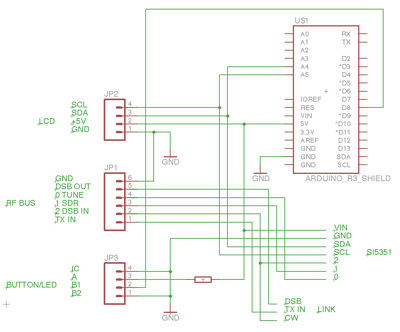
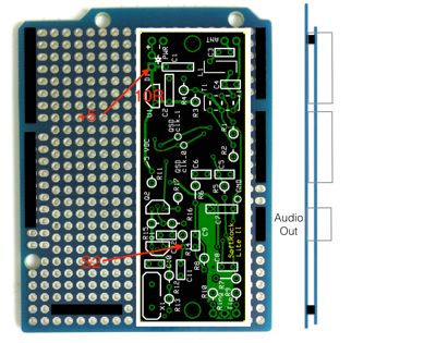
Physical connections

The setup described here is for an iMac, which has audio output (LS) and a built-in microphone, but no audio line-in. So an A-to-D/D-to-A convertor is used to provide wideband input/output audio channels. I use the Berlingher FCA202, which interfaces the iMac by Firewire (Apple persistently keeps messing around with their I/O protocols, so a couple of convertors are needed to convert the iMac's Thunderbolt to Firewire 800, then Firewire 800 to 400... £40-50!!!). The FCA202 has line-in which is the receive audio from the SDR and line-out which is the transmit audio to the SDR.

[If you lash out and buy a new MacBook it has only one I/O connector. The best solution here is to use an external A/D D/A convertor, e.g. the StarTech (look on Amazon), and connect with a USB-C to USB converter]

The computer microphone and LS are used for TX & RX listening.

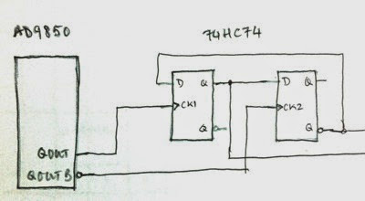
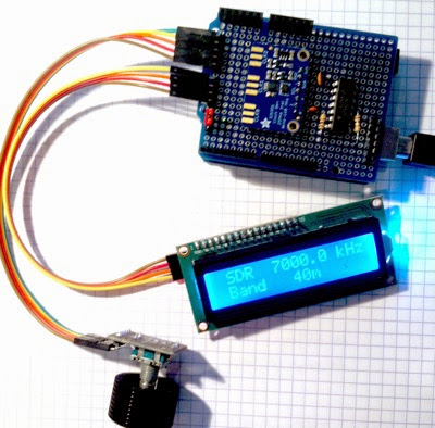
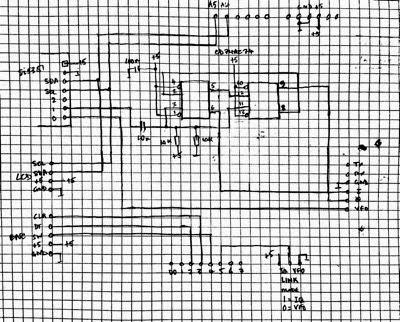
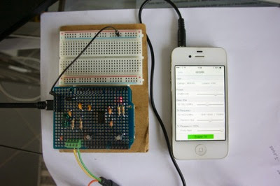
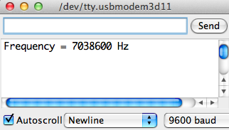
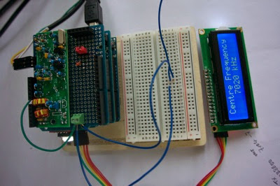
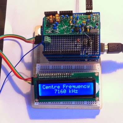
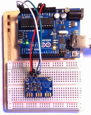
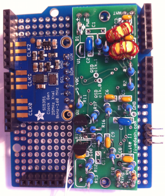
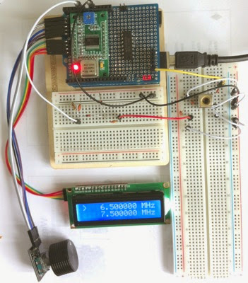
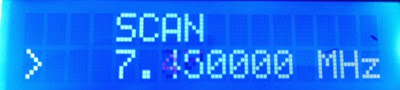
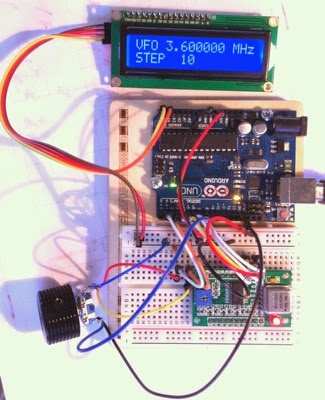
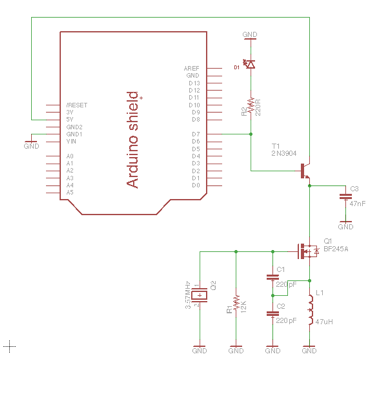
I have tested the setup, so far, only with a simple SDR receiver board, the Softrock Lite. I modified this as described in a earlier posting to use a VFO built round an Arduino and DDS board. But the original with fixed XTAL control works just as well.

Audio MIDI Setup

The first thing to do is to set up the iMac audio channels using the utility Audio MIDI Setup. This is used to create an "Aggregate" device and connect the FCA202, Built-in Microphone and Built-in Output. To do this click on the '+' button lower left and select Aggregate device. Name this something like "SDR"

Screen Shot 2014 11 18 at 14 51 34

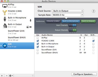
Make sure all the audio channels are set to 96kHz bandwidth, which will give the SDR about +/-48kHz tuning range.

DSP Radio setup

I am using the version 1.3.9 of DSP Radio as I have found bugs in the later version which I have yet to overcome. Launch the program and hit CTRL-A which will list the audio devices found on your iMac.

Screen Shot 2014 11 18 at 14 54 56

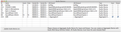
You can see here the Aggregate device you created in Audio MIDI Setup. Chose this for both Input and Output.

Next hit CTRL-C to create the RX & TX configurations. This means choosing the input/output channels for each, and setting the gain for the RX channel. The audio channels are, unfortunately not numbered the same as the numbers in Audio MIDI setup, so follow those shown here.

Screen Shot 2014 11 19 at 10 34 24

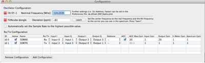
You can switch the AGC function on and off by clicking in the box, you can also set the input or output gain, the S-Meter gain and the gain applied to the spectrum display.

Using the DSP Radio

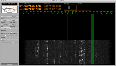
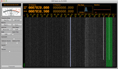
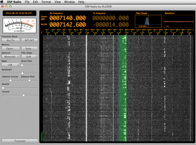
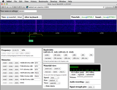
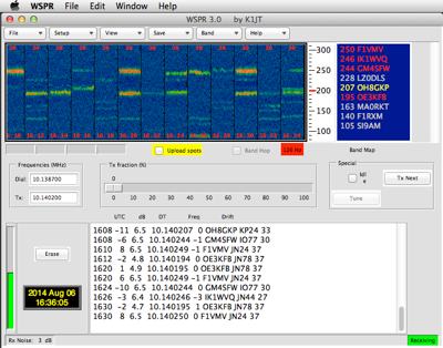
DSP Radio looks like this

Screen Shot 2014 11 19 at 10 37 00

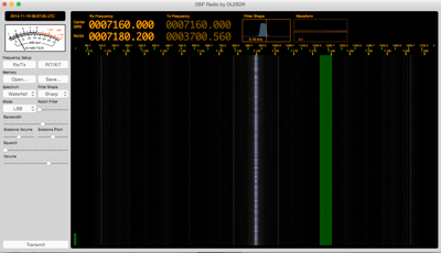
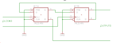
On reception the spectrum displays, and you can listen to, stations about +/- 45-48kHz from the centre frequency of the oscillator on your SDR radio. Set the centre frequency by scrubbing up/down on RX Frequency/Centre QRG or double click and enter the value in kHz. SDR radios that work receiving commands from the computer over a USB connection, like the Softrock Ensemble, will tune themselves to the frequency entered. If you do not have USB control (as in the Softrock Lite RX which I am using) then you must set the Centre Frequency to the local oscillator frequency on the receiver (remember that the receiver operates at a frequency of the XTAL divided by four as it has a /4 Johnson counter to generate the internal quadrature signals for the detector).

Select the mode, for example LSB, you should now see received signals and moving the green band across the display with the mouse will allow you to listen to the stations. The filter bandwidth can be chosen by sliding the Bandwidth slider.

If you have a transmit also SDR then you must set the RIT/XIT frequency to be the same as the indicate RX frequency, do this by clicking on the button RIT/XIT and enter the receive frequency, then click on RIT/XIT again. This will set the TX frequency to the same value as the RX frequency.

Transmit

To transmit you hit the SPACE bar or the button at the bottom on the display. The DSP Radio will generate an output audio frequency the same as the receive frequency, with sideband modulation set by the mode. For example, with a Centre Frequency QRG of 7160kHz, and LSB selected, tuning to an RX frequency of 7187.100kHz and sending a 1000Hz tome will generate a TX audio output via the D-to-A convertor of 16.1kHz, thus generating a carrier output of 7186.100kHz (7160,00 + 16.1kHz.

Screen Shot 2014 11 19 at 10 50 57

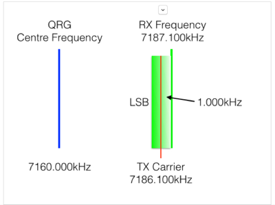
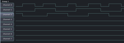
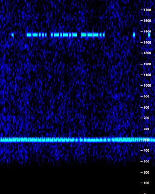
The display will show the transmitted signals, which would look like this

Screen Shot 2014 11 19 at 10 51 45

Comments

SDR is the future, and once you have used an SDR radio you will not want to go back. The HUGE advantage is the ability to see all the stations and relative signal strengths across a wide part of the band. When tuning to a station you can clearly see the bandwidth it is occupying and get a picture of the audio quality. It also make it easy to chose an unused channel if you wish to make a CQ call.

Saturday 15 November 2014

SDR first steps - the DDS

This is a new build of a DDS using the Adafruit Si5351 module. It adds a CD74ACT74 as a divide-by-four Johnson counter to generate IQ quadrature signals.

The DDS has two modes, SDR & VFO. It is tuned in programable steps (at the moment 10kHz for SDR & 100Hz for VFO) . The shield RF Bus outputs VFO and I & Q which are derived like this:

freq = indicated frequency on display

D5 HIGH	SDR mode	freq x4 clk0 = VFO x4 output
			freq x4 clk1 = Johnson /4 = I & Q x1 outputs
D5 LOW	VFO mode	freq x1 clk0 = VFO output


The input for tuning is a rotary encoder. An LCD display shows the band and the tuned frequency.

Three bands are generated, 40, 30, & 20m. These are selected in turn by the rotary encoder push button. Selecting a new band tunes a preset band frequency.

Photo 11 22 2014 13 38 00

The 5 connections across the left are for the Rotary Encoder and its Button and 4 for the I2C LCD display. This is documented in the source code.

The schematic diagram is:

Scanner Pro 1

Software

The software is a "Universal VFO" this software uses the new "Si5351.h" library from NT7S and implements a VFO switchable to 40, 30, & 20m bands. At the top of the code are defined constants, SDR & VFO, which determine the output frequency, x4 or x1. This value is set to SDR if you want an output x4 the indicated frequency on the VFO output, and a x4 drive to the onboard CD74ACT74 Johnson counter to generate I & Q signals. The VFO output in SDR mode can be used, for example, for the Softrock Lite SDR board. In VFO mode it changes to a single x1 output on the VFO RF bus pin.
The mode, SDR or VFO, is selected by a High or Low on pin D5, selected at start-up by the red jumper link. The constant STEP4 or STEP1 determine the step of the tuning, which can be, for example, 10kHz for driving an SDR, or 100Hz for a direct tuned radio.

The board thus has a VFO output which can be x1 or x4 the indicated frequency. When the hardware /4 Johnson counter is implemented and used, then two further outputs I & Q, provide outputs with the Si5351 running at x4 the frequency displayed. The VFO output is from CLK0, the IQ drive is from CLK1. Board outputs VFO, I & Q are on the RF bus (see previous post below).

Thus this design, with small changes in the software can satisfy diverse applications. Here's the code:

// Universal VFO, outputs for 40-30-20m
// V0.9
// Function
// Generates VHF & IQ outputs.
// Si 5351 output is x1 or x4 displayed frequency.
// Frequency selected in programmable steps by rotary encoder. Button changes bands 40-30-20m
// Change of band sets new frequency to band
// LCD displays frequency in kHz and band
// -----
// Shield has RF bus with VFO, I & Q outputs
// Two modes, set by link (pin D5):
// SDR (D5 HIGH) outputs x4 from clk0 to VFO, & x1 quadrature to I & Q. 10kHz steps
// VFO (D5 LOW) outputs x1 on clk0 to VFO out, 100Hz steps
// -----
// DDS I2C SI5351 
// SCL = A5
// SDA = A4
// I2C address 0x60
// ------
// display I2C LCD 16 * 2
// o A5 SCL (y)
// o A4 SDA (or)
// o +5     (r)
// o GND    (bwn)
// I2C address 0x27
// -----
// encoder KY-040
// o D2 DT  (y)
// o D3 CLK (g)
// o D4 SW  (or)
// o +5     (r)
// o GND    (bwn)
//-----
// D12-D13 TX-RX enable
// D10-D11 band switch relays 40-30-20
// -----

// I2C, Si5351, LCD and Rotary Encoder libraries
#include "Wire.h"
#include "si5351.h"
#include "LiquidCrystal_I2C.h"
#include "Rotary.h"

// XTAL freq, PLL multiplier, outputs 0-2, IQ Mult, steps (Hz)
#define XTAL 25
#define MULT 36
#define SDR 4
#define VFO 1
#define STEP4 10000
#define STEP1 100

// SDR/VFO link pin 5, button pin 4, Rotary Encoder pins 2 & 3 (A & B)
#define LINK 5
#define BUTTON 4
#define ROTA 2
#define ROTB 3

// dds object
Si5351 dds;

// lcd object
LiquidCrystal_I2C lcd(0x27, 16, 2);

// Rotary Encoder object
Rotary rot = Rotary(ROTA, ROTB);

// start frequencies (Hz)
float bandStart[3] = {
  7000000, 10050000, 14000000};
char bandName[3][4] = {
  "40m", "30m", "20m"}; // band 0 = 40m, 1 = 30m, 2 = 20m

// band & freq, freq steps, mode
byte band;
float freq;
float steps;
byte mode;

void setup()
{
  // encoder, button, link, relays & TXRX pin config
  pinMode(ROTA, INPUT_PULLUP);
  pinMode(ROTB, INPUT_PULLUP);
  pinMode(BUTTON, INPUT_PULLUP);
  pinMode(LINK, INPUT_PULLUP); // default input = HIGH

  mode = digitalRead(LINK); // HIGH (default) = SDR, LOW = VFO
  if(mode == HIGH) steps = STEP4; // set steps STEP4 (SDR) or STEP1 (VFO)
  else steps = STEP1;

  dds.init(SI5351_CRYSTAL_LOAD_8PF); // init si5351

  lcd.init(); // init LCD & backlight
  lcd.backlight();

  // startup band & frequency
  band = 0; // 40m
  freq = bandStart[band];

  freqOut(freq);

  dispMenu(); // display menu
  dispFreq(freq); // display freq
  dispBand(bandName[band]); // display band
}

void loop()
{
  unsigned char dir; // tuning direction CW/CCW
  byte step;

  if(digitalRead(BUTTON) == LOW) // button pressed?
  {
    while(!digitalRead(BUTTON)); // wait for release
    if(band == 2) band = 0; // go around
    else band++;

    freq = bandStart[band]; // set centre freq of new band

    freqOut(freq); 
    dispFreq(freq); // update freq & band display
    dispBand(bandName[band]); 
  }

  dir = rot.process(); // read encoder
  if(dir != DIR_NONE) // turned?
  {
    if(dir == DIR_CW) freq += steps; // increment +/- STEP
    if(dir == DIR_CCW) freq -= steps;

    freqOut(freq);
    dispFreq(freq); // update freq display
  }
}

// freq out x IQ
void freqOut(float freq)
{
  if(mode == HIGH) // SDR mode
  {
    dds.set_freq(freq * SDR, 0, SI5351_CLK0); // VFO out, x4
    dds.set_freq(freq * SDR, 1, SI5351_CLK1); // CD74AC74 quadrature to I & Q
  }
  else
  {
    dds.set_freq(freq * VFO, 0, SI5351_CLK0); // direct VFO out, x1
  }
}

// display menu
void dispMenu()
{
  lcd.setCursor(1, 0); // display caption
  if(mode == HIGH)  lcd.print("SDR");
  else lcd.print("VFO");
  lcd.setCursor(1, 1);
  lcd.print("Band");
}

// display freq
void dispFreq(float f)
{
  float pf;
  pf = f /1000; // kHz

  lcd.setCursor(5, 0);
  lcd.print("       "); // clear last freq display
  if(pf < 9999.9) lcd.setCursor(6, 0);
  else lcd.setCursor(5, 0);
  lcd.print(pf, 1);
  lcd.setCursor(13, 0);
  lcd.print("kHz");
}

// display band
void dispBand(char b[])
{
  lcd.setCursor(5, 1);
  lcd.print("   "); // clear last band display
  lcd.print(b);
}


Saturday 27 September 2014

QRSS first looks

I have a growing interest in the communication protocols called WSPR (see previous posting) and QRSS which stands for very slow morse code. I have often wondered if there is much activity on the bands. There are designated frequencies for QRSS which are:

WSPR  QRSS Frequencies

But how about software. QRSS needs basically a spectrum analyser for the audio spectrum, say from 0 to 2500Hz,, and a slow graphing of the signals received across the page. There are a few Windows based programs for QRSS reception but not a single one for the Mac (hey-ho). But their is one for the iPad from Black Cat Systems, called Godaloss (whatever..).

So i downloaded this (£1.99 on the App Store) and rigged up my iPad to the audio output of my iMac, via an A to D convertor iMic (which I can strongly recommend to anyone needing analog In or Out to USB conversion), it has two input sensitivity settings for Line and Mic. The iMic is powered by the battery in the iPad and interfaced using an Apple iPad 30pin to USB convertor.

Next I opened my browser (Safari - the browser must be HTML5 compatible) and went to the on-line site for an SDR receiver in Holland. Tuning to the 7MHz QRSS frequency revealed a number of morse code looking signals, although as of now I have had difficulty reading or understanding the code sent, they are clearly morse, like this:

IMG 0038

The signals at the bottom is, I think, a WSPR transmission.

I intend to experiment further, and use my own Arduino based SDR receiver to get to grips with QRSS. Then I may try myself to send some signals out into the ether.

Saturday 30 August 2014

WSPR generation

I have tried out my idea for a WSPR setup. This is an Arduino with a AD9850 DDS generating the transmit carrier, with a DSB mixer attached. The audio input comes from an iPhone app iWSPR. I had to "trim" the DDS frequency up a bit to get it to send at 7040100 (1500 kHz modulation on a 7038600 carrier).

DSC 1166

Screen Shot 2014 08 30 at 11 12 51

The receive is my recently built SDR. the output goes to the iMac through an FCA202 ADC running at 48kHz. The receiver software is the excellent DSP Radio, and this pipes its audio output via Soundflower to the WSPR program.

DSC 1168

Screen Shot 2014 08 30 at 11 15 03

Screen Shot 2014 08 30 at 11 16 20

The real thing

Now I changed the input to the mixer to come from the WSPR software running on the iMac via the FCA202. Then I switched on the "Upload Spots". The result is, amazingly, this:

Screen Shot 2014 09 05 at 14 52 42

Thursday 28 August 2014

The Softrock + Arduino SDR

So here is the final SDR hardware and the software code

Photo 09 03 2014 09 50 32
The white-yellow-red wires at the top are the audio output which I am feeding to a FCA202 ADC.

On the right you can see a 6 pin connector. This is a plagiarism of M0XPD's "RF bus", but carrying different signals as you can see below.

Schematic

Screen Shot 2014 08 29 at 14 47 55
The Softrock Lite ll SDR is driven with the output "TUNE" (0 output of the SI5351 module). The frequency can be set from 7000kHz to 7200kHz in 20kHz steps, but pushing the button on the left side. This sets the centre frequency of the display in DSP Radio running on the iMac.

DSP Radio listening to GB100ZZ the special event station, on 40m, celebrating Marconi transmissions from Devon UK.

Screen Shot 2014 08 29 at 14 42 51 Code

// SI5351 dds with LCD display, output is x4 display frequency to drive /4 IQ generator
// ------
// DDS I2C SI5351 
// SCL = A5
// SDA = A4
// address 0x60
// ------
// display I2C LCD 16 * 2
// o A5 SCL
// o A4 SDA
// o GND
// o +5
// address 0x27
// ------
// RF bus
// o GND
// o from DSB
// o TUNE out 0
// o SDR out 1
// o to DSB out 2
// o to TX out 2 CW/QRSS or DSB/WSPR

#include "Wire.h"
#include "Adafruit_SI5351.h"
#include "LiquidCrystal_I2C.h"

// PLL frequency, IQ multiplier
#define XTAL 25
#define MULT 28
#define IQ 4

// outputs
#define TUNE 0
#define SDR 1
#define CWDSB 2

// button pin 8
#define BUTTON 8

// dds object
Adafruit_SI5351 dds = Adafruit_SI5351();

// LCD object
LiquidCrystal_I2C lcd(0x27, 16, 2); 

float freq = 7000; // start TUNE freq kHz
float prevfreq;


void setup()
{ 
  pinMode(BUTTON, INPUT_PULLUP); // button input

  lcd.init();
  lcd.backlight();

  dds.begin();
  dds.setupPLLInt(SI5351_PLL_A, 28); // PLLA = 25 * 28 = 700MHz

  ddsout(freq);
  prevfreq = freq;
  show(freq); // display current TUNE frequency
}

void loop()
{
  if(digitalRead(BUTTON) == LOW) // button pressed?
  {
    while(!digitalRead(BUTTON)); // wait button release

    if(freq == 7200) // if top of band
    {
      freq = 7000; // go to bottom
    }
    else
    {
      freq += 20; // increment by 20kHz
    }
  }

  if(freq != prevfreq) // if changed update
    ddsout(freq);
  show(freq);
  prevfreq = freq;
}

void ddsout(float f)
{
  float plla; // PLLA freq
  float frac;
  float synth;
  long n;
  long m;
  int div;

  m = 100000;

  plla = XTAL * MULT; // 700MHz
  synth = plla/(freq/1000 * IQ); // MHz, x4 for IQ gen
  div = (int)synth; // get integer part
  frac = (synth - div) * m; // get fractional part
  n = (long) frac;

  dds.setupMultisynth(TUNE, SI5351_PLL_A, div, n, m); // out TUNE = PLLA/(div+n/m)
  dds.enableOutputs(true);
}

// display freq in MHz
void show(float f)
{
  lcd.setCursor(0, 0);
  lcd.print("Centre Frequency");

  lcd.setCursor(4, 1);
  lcd.print(f, 0);
  lcd.setCursor(9, 1);
  lcd.print("kHz");
}


Monday 25 August 2014

NEW NEW NEW! A great Digital Frequency Synthesiser

I was browsing the Arduino news the other day when I came across a new product from Adafruit.

Screen Shot 2014 08 25 at 16 36 22

Screen Shot 2014 08 25 at 16 36 28

It uses a very small SI5351 which is a PLL locked to a crystal, and subsequently divided down to the output you want. It has two PLLs and three outputs, all separately programmable.

Here's the very simple connections:

Photo 08 25 2014 16 32 29

What I have in mind is to squeeze a Softrock Lite ll SDR radio and one of these onto an Arduino shield to make a complete tuneable SDR. Unfortunately my build of the Softrock went wrong as I mounted the FST3253 IC up-side-down! Now I am waiting for replacement parts.

Screen Shot 2014 08 25 at 16 47 02

Code

// SI5351 dds

#include "Wire.h"
#include "Adafruit_SI5351.h"

// PLL frequency
#define XTAL 25
#define MULT 28

// dds object
Adafruit_SI5351 dds = Adafruit_SI5351();

float pll; // PLL freq
float freq = 3.6; // requested output freq

void setup()
{ 
  Serial.begin(9600);

  dds.begin();
  dds.setupPLLInt(SI5351_PLL_A, 28); // PLL = 25 * 28 = 700MHz
  
  Serial.println(freq);
}

void loop()
{


  float frac;
  float synth;
  long n;
  long m;
  int div;

  m = 100000;

  pll = XTAL * MULT;
  synth = pll/freq;
  div = (int)synth; // get integer part
  frac = (synth - div) * 100000; // get fractional part
  n = (long) frac;

Serial.print("Frequency = ");
Serial.println(freq);

  dds.setupMultisynth(0, SI5351_PLL_A, div, n, m); // out = PLL/(div+n/m)
  dds.enableOutputs(true);
  
  freq = get(); // get input freq MHz
}

// get input as an float
float get()
{
  float in;

  while(Serial.available() > 0)
    Serial.read();
    
  while(Serial.available()  == 0) 
    in = Serial.parseFloat();
    
  return in;
}

Friday 22 August 2014

Response plotter

I had a quick idea yesterday. To take an AD9850, set a start and end frequencies, and a step frequency. Then drive it to step from start to end.

The output would then be fed to a tuned circuit, and the response measured by an RF probe and fed to the analog input of the Arduino.

The Analog input would be plotted against frequency to show the tuned circuit's response curve.

Here's the setup:

Photo 08 21 2014 14 49 37

The control is the rotary encoder. First turn it to select the start frequency, then push the button, now select the end frequency. A further push starts the scan. Like this

Photo 08 21 2014 14 43 29

Photo 08 21 2014 14 43 43

The result is shown on the Monitor, like this

Screen Shot 2014 08 21 at 14 41 59

Code

// CONNECTIONS
// A5-A0 side
// ------
// encoder KY-040
// o Grey 2 CK
// o White 3 DT
// o Blue 8 SW
// o Violet +5
// o Black GND
//
// display I2C LCD 16 * 2
// o Green A5 SCL
// o Yellow A4 SDA
// o Red GND
// o Orange +5
// ------
// D0-D13 side
//
// RF bus hardware output
// o GND
// o DSB out
// o I to SDR
// o Q to SDR
// o S0 to DSB in
// o S1 to TX (selectable S1 ad9850 or DSB out)
//
// selector output to S1: CW-S1-DSB 

#include "Encoder.h"
#include "DDS.h"
#include "Wire.h"
#include "LiquidCrystal_I2C.h"

// encoder pin connections and +5V & GND
#define CK 2
#define DT 3
#define BUTTON 8   // pin Button

// DDS pin connections
#define RST  4     // Pin  RST
#define DATA 5     // Pin  DATA
#define FQ   6     // Pin  FQ
#define CLK  7     // Pin  CLK

// input connection
#define IN A0

// I2C connections
#define SDA A4
#define SCL A5

// commands
#define SF 0 // set start freq
#define EF 1 // set end freq
#define SC 2 // scan start

// output print scale factor
#define FACTOR 2 

// Encoder object
Encoder enc(DT, CK);

// DDS object
DDS dds(CLK, FQ, DATA, RST);

// LCD object
LiquidCrystal_I2C lcd(0x27, 16, 2); 

double freq; // scan frequency
double freq1 = 6500000L; // init start & end
double freq2 = 7500000L;
long tune = 10000L; // fix button tune step and scan delta steps
long delta = 50000L;
long pos = 0; // enc positions
long newpos;
byte act = 0; // init set freq1

void setup()
{
  pinMode(BUTTON, INPUT_PULLUP); // button input

  Serial.begin(9600); // serial comms

  enc.write(0); // init encoder

  dds.init(); // init DDS
  dds.setFrequency(freq1); // set start freq

  lcd.init(); // init LCD
  lcd.backlight();
}

void loop()
{  
  byte tag;

  if(digitalRead(BUTTON) == LOW) // button pressed?
  {
    while(!digitalRead(BUTTON)); // wait for button release
    if(act == 2) act = 0; // chose actions
    else act++;
  }
  switch(act) // change delta freq
  {
  case SF: // change start freq1 in 100kHz steps
    tag = 0;
    freq1 = change(freq1);
    break;
  case EF: // change end freq2 in 100kHz steps
    tag = 1;
    freq2 = change(freq2);
    break;
  case SC: // start scan
    tag = 2;
    for(freq = freq1; freq <= freq2; freq += delta)
    { 
      delay(50);
      dds.setFrequency(freq); // output freq
      show(tag, freq1, freq); // display scan freq
      volts(freq, analogRead(IN)); // output to monitor
    }
    act = 0;
    break;
  }
  show(tag, freq1, freq2);
}

// change freq, returns new freq
long change(long f)
{
  // encoder read, updates freq
  newpos = enc.read();
  if(newpos != pos)
    f += tune * (newpos - pos) / 4; // enc gives 4 pulses per click!
  pos = newpos;
  return f;
}

// display start & end freqs in MHz
void show(byte t, double f1, double f2)
{ 
  if(t == 0) // line 1 delete ">", line 0 put ">"
  {
    lcd.setCursor(0,1);
    lcd.print(" ");
    lcd.setCursor(0,0);
    lcd.print(">");
  }
  if(t == 1) // line 0 delete ">", line 1 put ">"
  {
    lcd.setCursor(0,0);
    lcd.print(" ");
    lcd.setCursor(0,1);
    lcd.print(">");
  }

  if(t == 0 || t == 1) // line 0 f1 or "SCAN"
  {
    lcd.setCursor(4,0);
    lcd.print(f1/1000000, 6);
    lcd.setCursor(13,0);
    lcd.print("MHz");
  }
  else if(t == 2)
  {
    lcd.setCursor(4,0);
    lcd.print("SCAN         ");
  }

  lcd.setCursor(4,1);
  lcd.print(f2/1000000, 6);
  lcd.setCursor(13,1);
  lcd.print("MHz");
}

// output freq & A0 to monitor
void volts(long f, int in)
{  
  int n;

  Serial.print(f);
  n = in/FACTOR;
  while(n-- > 0)
  {
    Serial.print(" ");
  }
  Serial.println("X");
}

SDR - this is what I will do

I have struggled to build an SDR for the Arduino DDS board to tune. So I have decided to get someone else's design and mount it on an shield board.

The simple, obvious choice is the Softrock Lite ll from Tony Parks. This is a basic SDR which is what I want to build anyway, but it is debugged and ready to go. So here' what I propose.

1. Crop the schematic to accept an input from the AD9850 DDS shield I have built.

SDR schematic

2. Then plan a shield like this

SDR shield

I have ordered a kit from SDR-Kits as Fivedash are out of stock at the moment - coming soon they say...

Can't wait to see how it goes.

Wednesday 6 August 2014

WSPR - whisper

WSPR is a very low power, very slow way of transmitting some key information. It is used to test propagation conditions. You have your own WSPR transmitter, and other people will receive you. The reception data is collected on a web site and you can get an immediate map of where you are being received.

I have got a WSPR system for reception going here.

I use my browser, Safari, and connect to the web SDR receiver at websdr.ewi.utwente.nl:8901. Then I pipe the output of Safari, normally connected to the system Internal Speakers, to SoundFlower (2ch).

Screen Shot 2014 08 06 at 17 36 31

The input to the WSPR program is taken from SoundFlower (2ch) and so it receives the sound from the SDR radio.

Screen Shot 2014 08 06 at 17 35 59

This is the result.

Tuesday 5 August 2014

Arduino breadboard proto

I searched the web for ages to try to find a simple Arduino blank proto board. So many of them have added items like a reset button, LED, area to mount an SO IC chip, etc etc.

But if you want a plain proto board you can get one...

Photo 08 05 2014 11 46 16

,,. from Electan:

Screen Shot 2014 08 05 at 11 54 59

Now that is useful!

Monday 4 August 2014

LCD using I2C serial access

I have been struggling for days to try to get my LCD 1602 display, with an I2C interface board on the back, working.

To do this one needs a library called "LiquidCrystal_I2C.h" which is referenced in many places on the web. But it seems a shambles as many of the sources have modified the library code to suit a particular application and they simply don't work. I downloaded at least 5 different versions none of which worked, and my LCD just showed a line of white rectangles, nothing else.

I have now found a version of the library which works!! So if you have the same difficulty go over to the site of HobbyComponents, search for their LCD display with I2C interface, then go to the forum and there you will find a download of the library which works.

Good luck!

Saturday 2 August 2014

DDS AD9850 with encoder input and LCD display

Here's a sketch to use an AD9850 DDS with input from an encoder and output to an LCD display. This sketch will be further developed to display more parameters and to have inputs to change the scanning speed. The current one, here, increments the frequency by 10, 100, 1kHz or 10kHz per step when you press the encoder knob, not the most practical way to tune a radio.. will have to give this some thought.

Photo 08 06 2014 11 16 42

// DDS AD9850, encoder input
// display on LCD 16 * 2
// encoder A = 2, C (centre) = GND & B = 3

#include "DDS.h"
#include "Wire.h"
#include "LiquidCrystal_I2C.h"

#define ENCA 2
#define ENCB 3
// pin connections
#define RST  4     // Pin  RST
#define DATA 5     // Pin  DATA
#define FQ   6     // Pin  FQ
#define CLK  7     // Pin  CLK

#define BUTTON 8   // pin Button

// frequency change, by df
#define NC 0
#define UP 1
#define DWN 2

// I2C connections
#define SDA A4
#define SCL A5

// DDS object
DDS dds(CLK, FQ, DATA, RST);

// LCD object
LiquidCrystal_I2C lcd(0x27, 16, 2); 

double freq = 3600000L; // start freq Hz
double df = 100; // 100Hz change in frequency per click
byte chg = NC;   // flag NC = no change, UP = add df, DWN = subtract df
byte dsw = 0;    // delta freq = 10Hz

char *dtxt[4] = {
  " 10", "100", " 1K", "10K"}; // delta freq display values

void setup()
{

  pinMode(ENCA, INPUT_PULLUP); // encoder inputs
  pinMode(ENCB, INPUT_PULLUP);

  pinMode(BUTTON, INPUT_PULLUP); // button input
  
  attachInterrupt(0, doEnc, CHANGE); // interrupt on any change of pin 2

  dds.init();
  dds.setFrequency(freq);

  lcd.init();
  lcd.backlight();
  show(freq);
}

void loop()
{  
  int state;
  
  switch (chg)
  {
  case NC:
    break;
  case UP:
    freq += df;
    show(freq);
    break;
  case DWN:
    freq -= df;
    show(freq);
    break;
  }
  chg = NC;
  dds.setFrequency(freq);
  
  if(digitalRead(BUTTON) == LOW) // button pressed?
  {
    if(dsw == 3) dsw = 0;
    else dsw++;
  }
  switch(dsw)
  {
  case 0:
    df = 10;
    break;
  case 1:
    df = 100;
    break;
  case 2:
    df = 1000;
    break;
  case 3:
    df = 10000;
    break;
  }
  while(!digitalRead(BUTTON)); // wait for button release
  showd(dsw);

}

// display freq in MHz
void show(double f)
{
  lcd.setCursor(0, 0);
  lcd.print("VHF"); 

  lcd.setCursor(4, 0);
  lcd.print(f/1000000, 6);
  lcd.setCursor(13,0);
  lcd.print("MHz");
}

// display delta freq
void showd(byte d)
{
  lcd.setCursor(0, 1);
  lcd.print("STEP");
  lcd.setCursor(5,1);
  lcd.print(dtxt[d]);
}

void doEnc()
{
  if(digitalRead(ENCA) == digitalRead(ENCB))
    chg = UP;
  else
    chg = DWN;
}

DDS AD9850 Serial I/O

This is a simple sketch to use the AD9850 DDS with input from the keyboard (frequency in Hz) and display of the output frequency on the IDE Monitor.

// DDS AD9850, keyboard frequency input, use DDS library
// set Monitor for "Newline" 9600 baud

#include "DDS.h"

// pin connections
#define RST  4     // Pin  RST
#define DATA 5     // Pin  DATA
#define FQ   6     // Pin  FQ
#define CLK  7     // Pin  CLK

// DDS object
DDS dds(CLK, FQ, DATA, RST);

// start frequency
double newfreq = 7100000L; // 7.1MHz

void setup()
{

  Serial.begin(9600);
  while(!Serial);
  
  dds.init();
  dds.setFrequency(newfreq);
}

void loop()
{
  double freq;

  freq = newfreq;
  
  Serial.print("Frequency = ");
  Serial.print(freq);
  Serial.println(" Hz");

  newfreq = (double)get();

  if(newfreq != freq)
    dds.setFrequency(newfreq);
}

// get input as a float
float get()
{
  float n;

  while(Serial.available() > 0)
    Serial.read();
  while(Serial.available()  == 0) 
    n = Serial.parseFloat();
  return n;
}


Wednesday 16 July 2014

Mouse in a labyrinth sketch

When it comes to labyrinths there are more challenges than simply avoiding walls in a box. The mouse needs to follow walls, when they are on both sides and when the wall is only one side. It also needs to detect when it reaches a turning with a wall in front of it, make the correct turn, and continue along the new hallway.

The code below is NOT perfect and my mouse lurches a bit, especially after turns and entering the new hall way. I have not yet found out why...

This sketch uses a different MouseSensors.h file to the box sketch so take care! It needs to do this as instead of the events being detected at a fixed distance (DETECT) two variables are use for the side and front distances. A further variable is used for the detection of walls. These variables are set by a call to the sketch calibrate() function. The mouse reads the side distances, then turns east and measures the front distance and the wall distance with one side absent.

I use a Bluetooth module connected to Arduino pins 0 & 1 to send data back to the Mac. I use the program CoolTerm on the Mac to display the readings from the function printsens().

Screen Shot 2014 07 16 at 17 14 05

Here's my mouse in a simple labyrinth:

Photo 16 07 2014 16 59 06  HDR

and here's the code in three parts: the ".ino" sketch and the two ".h" class files for motors and sensors:

MOUSELABRTYNTH.INO

/* MouseLabrynth *** MASTE R FILE *** 16-7-14
his program tracks through a Labrynth - 
that is a twisted, closed pathway with the goal at the end  
 */

#include 
#include "MouseMotors.h"
#include "MouseSensors.h"

// `LED & button
#define LED 13
#define BUTTON 12

// proportional multiplier (float), KP1 for hall, KP2 for sides
#define KP1 0.25
#define KP2 2.5

MouseMotors motors; // motors object
MouseSensors sensors; // pass pin numbers to sensors object

// event returned by state()
byte event;

void setup()
{
  Serial.begin(9600);

  motors.attach(); // attach servos

  sensors.enable(); // enable emitter pins

  pinMode(BUTTON, INPUT_PULLUP); // button input
  pinMode(LED, OUTPUT); // LED output

  digitalWrite(LED, LOW);
  while(digitalRead(BUTTON)); // wait for button press
  delay(100);
  while(!digitalRead(BUTTON)); // wait for button release
  digitalWrite(LED, HIGH);

  // place mouse between walls to calibrate, then push button
  calibrate(); // get front, and side limits for sensors.state
}

void loop()
{ 
  printsens(); // temp DEBUG code

  labNav(sensors.state());
}

// Navigate the labarynth based on event returned by state() function
// events map
//     7
//  3  1  5
// 2   6   4
void labNav(byte event)
{ 
  switch(event) // get event
  {
  case 0: // no event or north only
  case 1:
    motors.halt();
    error();
    break;
  case 2: // wall to west
    fwdNav();
    break;
  case 3: // walls west & north
    motors.turn(E, 90);
    sensors.init();
    break;
  case 4: // wall est
    fwdNav();
    break;
  case 5: // walls west & east
    motors.turn(W, 90);
    sensors.init();
    break;
  case 6: // walls north & east
    fwdNav();
    break;
  case 7: // walls all round
    motors.halt();
    error();
    break;
  }
}

// go forwards checking sides
// if L&R stay in centre, if L or R follow it, if none go strait
// Threshold thset is found by calibrate() 
void fwdNav()
{

  while(sensors.north < sensors.front) // while no wall north
  {
    sensors.sense();

    if(sensors.west > sensors.wall && sensors.east > sensors.wall) // walls west & east
    {
      motors.fwd(0, KP1 * (float)(sensors.east - sensors.west)); // error is a float
    }
    else if(sensors.east < sensors.wall) // no east wall
    {
      motors.fwd(0, KP2 * (float)(sensors.side - sensors.west)); // follow west wall
    }
    else if(sensors.west < sensors.wall) // no west wall
    {
      motors.fwd(0, KP2 * (float)(sensors.east - sensors.side)); // follow east wall
    }
    else
    {
      motors.fwd(0, 0); // just go forwards
    }
  }
}

// get side width, north and wall limits
void calibrate()
{
  sensors.init(); // read sensors
  sensors.side = (sensors.east + sensors.west)/2; // set side limit

  motors.turn(E, 90); // turn east

  sensors.init(); // re-read sensors
  sensors.front = sensors.north; // set north limit
  sensors.wall = (sensors.side + sensors.west) / 2; // detect wall limit

  motors.turn(W, 90); // turn back west

  sensors.init(); // initialise sensors. west, north, east
}

void error()
{
  while(true)
  {
    digitalWrite(LED, HIGH);
    delay(100);
    digitalWrite(LED, LOW);
    delay(100);
  }
}

// DEBUG, print sensors data
void printsens()
{

  Serial.print("\n front wall    side   W      N      E      event\n");
  Serial.print(sensors.front);
  Serial.print("\t");
  Serial.print(sensors.wall);
  Serial.print("\t");
  Serial.print(sensors.side);
  Serial.print("\t");
  Serial.print(sensors.west);
  Serial.print("\t");
  Serial.print(sensors.north);
  Serial.print("\t");
  Serial.print(sensors.east);
  Serial.print("\t");
  Serial.println(sensors.state());
}


MOUSEMOTORS

// *** MouseMotors MASTER FILE *** 16-7-14

#include 
#include 

// servo pins west & east
#define WS 10
#define ES 11

// servo HALT position, forward SPEED speed, TURN speed, ROTATION (ms/deg) 
// and CM (ms/cm)
#define HALT 1500
#define SPEED 30
#define TURN 30
#define ROTATE 13
#define CM 185

// sensor bits, event value
//   3 2 1 0
// N 0 0 0 1 = 1
// W 0 0 1 0 = 2
// E 0 1 0 0 = 4
// S 1 0 0 0 = 8
// events map
//     7
//  3  1  5
// 2       4
#define N  0 
#define W  1
#define E  2
#define S  3

Servo westServo; // left side
Servo eastServo; // right side

class MouseMotors
{

public:
  // attach servos to pins
  void attach()
  {
    westServo.attach(WS);
    eastServo.attach(ES);
  }

  // halts the motors
  void halt()
  {
    westServo.writeMicroseconds(HALT);
    eastServo.writeMicroseconds(HALT);
    delay(100); // wait 100 ms for inertia
  }

  // forward for dist (cm, 0 = continuous) error + W, error - E
  void fwd(byte dist, float error)
  {
    westServo.writeMicroseconds(HALT + SPEED - error);
    eastServo.writeMicroseconds(HALT - SPEED - error);
    if(dist != 0)
    {
      delay(CM * dist);
      halt();
    }
  }

  // turn in direction by degrees
  void turn(byte dir, byte deg) // turn in dir by deg
  {    
    switch (dir)
    {
    case W: // left
      westServo.writeMicroseconds(HALT - TURN);
      eastServo.writeMicroseconds(HALT - TURN);
      break;
    case E : // right
      westServo.writeMicroseconds(HALT + TURN);
      eastServo.writeMicroseconds(HALT + TURN);
      break;
    }
    delay(deg * ROTATE); // convert degrees to ms runtime
    halt();
  } 
};


MOUSESENSORS

// *** MouseSensors MASTER FILE version for mouselabrynth *** 16-7-14
// cellwalls and mouse direction use NWES, see bitmap below and event values

#include 

// sensor emitter and detector L, F & R pins
#define LE 2
#define LD A0
#define FE 3
#define FD A1
#define RE 4
#define RD A2

// wall ID, event
// N 0 0 0 1 = 1
// W 0 0 1 0 = 2
// E 0 1 0 0 = 4
// S 1 0 0 0 = 8
// events map
//     7
//  3  1  5
// 2   6   4

// wall ID bits
#define N  0 
#define W  1
#define E  2
#define S  3

// number of sensor reading to take for init
#define AVG 10

class MouseSensors
{
public:
  // sensor smoothed readings
  int west;
  int north;
  int east;

  // north wall detect, side distance & side walls detect
  int front;
  int side;
  int wall;

  // init ports
  void enable()
  {
    pinMode(LE, OUTPUT);
    pinMode(FE, OUTPUT);
    pinMode(RE, OUTPUT);
  }

  // read sensors, laod west, north & east ints
  void sense()
  {
    float comb;
    float amb;
    float refl;

    // WEST
    digitalWrite(LE, HIGH); // emitter on
    delay(1);
    comb = analogRead(LD); // save combined value
    digitalWrite(LE, LOW); // emitter off
    delay(1);
    amb = analogRead(LD); // save ambient value
    refl = comb - amb;// calculate reflected

    west = int(refl * 0.1 + west * 0.9);

    // NORTH
    digitalWrite(FE, HIGH); // emitter on
    delay(1);
    comb = analogRead(FD); // save combined value
    digitalWrite(FE, LOW); // emitter off
    delay(1);
    amb = analogRead(FD); // save ambient value
    refl = comb - amb;// calculate reflected

    north = int(refl * 0.1 + north * 0.9);

    // RIGHT
    digitalWrite(RE, HIGH); // emitter on
    delay(1);
    comb = analogRead(RD); // save combined value
    digitalWrite(RE, LOW); // emitter off
    delay(1);
    amb = analogRead(RD); // save ambient value
    refl = comb - amb;// calculate reflected    

    east = int(refl * 0.1 + east * 0.9);
  }

  // read sensors, return event byte (0 - 7)
  byte state()
  {
    byte event;
    byte detect;

    sense();

    event = 0; // init to zero

    if(north >= front) event +=1; // add 1
    if(west >= wall) event += 2;  // add 2
    if(east >= wall) event += 4;  // add 4

    return event;
  }

  // init sensors averages by calling sense() AVG times
  void init()
  {
    byte i;

    for(i = 0; i < AVG; i++)
      sense();
  }
};

Mouse in a box sketch

Here's the mousebox.ino sketch. This keeps the mouse in a box of walls, changing direction if it comes near a wall.

MOUSEBOX

/* *** mousebox skech *** 16-7-14
sketch to run mouse in a box without touching the sides
 makes random moves
 */
#include 
#include "MouseSensors.h"
#include "MouseMotors.h"


// LED & button pins
#define LED 13
#define BUTTON 12

MouseMotors motors; // create motors object
MouseSensors sensors; // pass pin numbers to sensors object

void setup()
{
  Serial.begin(9600); // start serial comms

  motors.attach(); // attach servos
  sensors.enable(); // enable emiiter ports

  pinMode(LED, OUTPUT); // LED output
  pinMode(BUTTON, INPUT_PULLUP); // input is from button pin to GND

  // *** START
  while(digitalRead(BUTTON)); // wait for button press
  delay(100);
  while(!digitalRead(BUTTON)); // wait for button release
  digitalWrite(LED, HIGH); // LED on is a go
}

void loop()
{ 
  // avoid walls of box
  avoid(sensors.state());
}

void avoid(byte event) // take avoiding action depending on sensor event
{
  switch(event)
  {
  case 1: // north
    motors.turn(W, 90);
    sensors.init();
    break;
  case 2:  // west & north west
  case 3:
    motors.turn(E, 45);
    sensors.init();
    break;
  case 4: // east and north east
  case 5:
    motors.turn(W, 45);
    sensors.init();
    break;
  case 6: // east & west
  case 7: // east, north & west
    motors.turn(E, 180);
    sensors.init(); 
  default:
    motors.fwd(0,0); // forwards, continuous, no error correction
  }
}

Friday 4 July 2014

Mouse Robot

Latest update 7-7-13

My Mouse Robot uses two continuous rotation servos and three IR emitter detectors pointing left, front and right. Acknowledgements to M Backus for the ideas and code principles.

The code that I have listed below are the classes, this will be followed in future posts by the application sketches.

Mouse sensors There are a number of IR emitters and detectors on the market, but the one I have had most success with is the TCRT5000 from Vishay.

Screen Shot 2014 07 04 at 10 58 21

This is a module with an IR emitter and IR phototransistor built in one package. The general wiring diagram for the eventual three detectors is:

Screen Shot 2014 07 04 at 10 35 41

The motors on the mouse are continuous rotation servos from Parallax.

LIBRARIES

There are two class files, for motors and sensors.

MOTORS

The calls to the motors class are:

motors.attach(); // connects the servo motors to the pins

motors.halt(); // stoops the motors

motors.fwd(dist, error); // motors forwards for diet (0 = continuous) with steering error

motors.turn(dir, deg); // turn West (left) or East (right) by degrees

// *** MouseMotors MASTER FILE *** 16-7-14

#include 
#include 

// servo pins
#define LS 10
#define RS 11

// servo HALT position, forward SPEED speed, TURN speed, ROTATION (ms/deg) 
// and CM (ms/cm)
#define HALT 1500
#define SPEED 30
#define TURN 30
#define ROTATE 13
#define CM 185

// proportional multiplier (float)
#define KP 0.5

// sensor bits, event value
//   3 2 1 0
// N 0 0 0 1 = 1
// W 0 0 1 0 = 2
// E 0 1 0 0 = 4
// S 1 0 0 0 = 8
// events map
//     7
//  3  1  5
// 2       4
#define N  0 
#define W  1
#define E  2
#define S  3

Servo leftServo;
Servo rightServo;

class MouseMotors
{

public:
  // attach servos to pins
  void attach()
  {
    leftServo.attach(LS);
    rightServo.attach(RS);
  }

  // halts the motors
  void halt()
  {
    leftServo.writeMicroseconds(HALT);
    rightServo.writeMicroseconds(HALT);
    delay(100); // wait 100 ms for inertia
  }

  // forward for dist (cm, 0 = continuous) error + W, error - E
  void fwd(byte dist, float error)
  {
    error = error * KP;
    leftServo.writeMicroseconds(HALT + SPEED -  error);
    rightServo.writeMicroseconds(HALT - SPEED -  error);
    if(dist != 0)
    {
      delay(CM * dist);
      halt();
    }
  }

  // turn in direction by degrees
  void turn(byte dir, byte deg) // turn in dir by deg
  {    
    switch (dir)
    {
    case W: // left
      leftServo.writeMicroseconds(HALT - TURN);
      rightServo.writeMicroseconds(HALT - TURN);
      break;
    case E : // right
      leftServo.writeMicroseconds(HALT + TURN);
      rightServo.writeMicroseconds(HALT + TURN);
      break;
    }
    delay(deg * ROTATE); // convert degrees to ms runtime
    halt();
  } 
};


SENSORS

The calls to the sensors class are:

sensors.sense(); // sense all three sensors and load west, north & east variables

sensors.state(); // returns an event (0-7) showing walls around the sensors

sensors.init(); // calls sense AVG times

sensors.calibrate(); // measured west and east sensors, takes average and sets thset distance for wall following

// *** MouseSensors MASTER FILE *** 16-7-14
// cellwalls and mouse direction use NWES, see bitmap below and event values
// this version is for mousebox.ino and uses a fixed detect distance in state()

#include 

// sensor emitter and detector L, F & R pins
#define LE 2
#define LD A0
#define FE 3
#define FD A1
#define RE 4
#define RD A2

// bitmap, event value
//   3 2 1 0
// N 0 0 0 1 = 1
// W 0 0 1 0 = 2
// E 0 1 0 0 = 4
// S 1 0 0 0 = 8
// resulting events map
//     7
//  3  1  5
// 2   6   4

#define N  0 
#define W  1
#define E  2
#define S  3

// number of sensor reading to take for init, event detect level
#define AVG 10
#define DETECT 20

class MouseSensors
{
public:
  // sensor smoothed readings
  int west;
  int north;
  int east;

  // threasholds for state() north detect and hall navigation
  int ndet;
  int hall;
  int wall;

  // init ports
  void enable()
  {
    pinMode(LE, OUTPUT);
    pinMode(FE, OUTPUT);
    pinMode(RE, OUTPUT);
  }

  // read sensors, laod west, north & east ints
  void sense()
  {
    float comb;
    float amb;
    float refl;

    // WEST
    digitalWrite(LE, HIGH); // emitter on
    delay(1);
    comb = analogRead(LD); // save combined value
    digitalWrite(LE, LOW); // emitter off
    delay(1);
    amb = analogRead(LD); // save ambient value
    refl = comb - amb;// calculate reflected

    west = int(refl * 0.1 + west * 0.9);

    // NORTH
    digitalWrite(FE, HIGH); // emitter on
    delay(1);
    comb = analogRead(FD); // save combined value
    digitalWrite(FE, LOW); // emitter off
    delay(1);
    amb = analogRead(FD); // save ambient value
    refl = comb - amb;// calculate reflected

    north = int(refl * 0.1 + north * 0.9);

    // RIGHT
    digitalWrite(RE, HIGH); // emitter on
    delay(1);
    comb = analogRead(RD); // save combined value
    digitalWrite(RE, LOW); // emitter off
    delay(1);
    amb = analogRead(RD); // save ambient value
    refl = comb - amb;// calculate reflected    

    east = int(refl * 0.1 + east * 0.9);
  }

  // read sensors, return event byte
  byte state()
  {
    byte event;
    byte detect;
    
    sense();
    
    detect = DETECT; // set detection limit
    event = 0; // init to zero

    if(north >= detect) bitSet(event, N); // 0001
    if(west >= detect) bitSet(event, W); // 0010
    if(east >= detect) bitSet(event, E); // 0100

    return event;
  }

  // init sensors averages by calling sense() AVG times
  void init()
  {
    byte i;

    for(i = 0; i < AVG; i++)
      sense();
  }
};

Sunday 1 June 2014

Fun little project at GB5BRA Banbury Show

The Banbury Amateur Radio Society will be at the annual Banbury show on Sunday 8th June. We will be operating a station GB5BRA and look forward to contacting you...

Also at the show we will be promoting amateur radio. For this we have a display panel "LEARN _ BUILD _ PLAY". And a tiny demo using an Arduino to send an automated morse message "CQ CQ CQ DE GB5BRA GB5BRA K".

Circuit

Screen Shot 2014 06 02 at 09 19 15 Here's the code:

// Morse transmitter, with oscillator 
// LED & OSC Pin 7

// output pin
#define LEDPIN 7

// text array codes
#define DOT 0
#define DASH 1
#define SPACE 2
#define WORD 3

// message words
int CQ[] = {1,0,1,0,2,1,1,0,1,3};
int DE[] = {1,0,0,2,0,3};
int GB5BRA[] = {1,1,0,2,1,0,0,0,2,0,0,0,0,0,2,1,0,0,0,2,0,1,0,2,0,1,3};
int K[] = {1,0,1,3};

// dash = 3 dots, space = 3 dots, word = 7 dots
#define DOTTIME 150

void setup() 
{
  pinMode(LEDPIN, OUTPUT);
}

void loop() 
{

// send message words, sends CQ CQ CQ DE GB5BRA GB5BRA K
  sender(CQ);
  sender(CQ);
  sender(CQ);
  sender(DE);
  sender(GB5BRA);
  sender(GB5BRA);
  sender(K);
  
  delay(2000); // repeat after 2 secs
}

// send a word
void sender(int dida[]) {

  int x = 0; // array index

// send characters up to end of word
  while(dida[x] != WORD) {
   switch (dida[x]) {
    case DOT:
       transmit(DOTTIME);
       delay(DOTTIME); // add after dot
       break;
    case DASH:
        transmit(3 * DOTTIME);
        delay(DOTTIME); // add after dash
        break;
    case SPACE:
         delay(2 * DOTTIME);  // add for space
         break;
    }
    x++;
  }
  delay(6 * DOTTIME); // add   for word
}

// transmit for time (msec)
void transmit(long time) {

  digitalWrite(LEDPIN, HIGH); // turn on LED
  delay(time); // time 
  digitalWrite(LEDPIN, LOW); // turn off LED
}


Update: Its a pity but the Banbury Show, where the project would be shown, was cancelled 3 days before it was due, because of a water logged field.

SI514 arrived from Silicon Labs

A big parcel was delivered yesterday.

2014 05 30 18 01 18

Inside was a smaller parcel.

2014 05 30 18 02 24

And inside that a small box.

2014 05 30 18 03 45

Containing two very small Si514 components!!!

2014 05 30 18 03 55

Thank you Silicon Labs for these free samples.

Friday 2 May 2014

Progress in SDR RX

So here's an update on the design of an Arduino Shield SDR RX.

First the AD9850 is no good, as it has not got 50:50 ratio output square waves. I need 50:50 to make my clock generator, which only divides by /2 not /4 of other designs - thus he VFO is half the frequency... and the Si570 is no good as it does not have complementary outputs. But the Si514 does, and this seems a good choice.

Screen Shot 2014 05 02 at 12 27 00

Screen Shot 2014 05 02 at 12 26 33

This is my circuit. The 7474 flip-flops and driven by complementary clock inputs and give quadrature output for the SDR switches (FST3253).

Screen Shot 2014 05 02 at 12 26 38
The complete circuit is this:

Screen Shot 2014 05 02 at 12 27 06

Monday 28 April 2014

AD9580 DDS for SDR

I think I have invented something new!!! What I am trying to do is to build an SDR on an Arduino shield, for this I thought of using a DDS frequency synthesiser and an FT3253 MOS switch - in a design similar to a lot found on the web.

The idea is to drive the AD9850 chip module from the Arduino and display the band and frequency on an LCD screen. (See previous posting). This all works fine.

The new idea was to take the square wave outputs from the AD9580 module and drive a couple of 7474 dividers, like this

2014 04 28 14 20 45

This is different from the usual circuit which drives the two clock inputs together, but which divides the input frequency by 4, here we divide by 2. This means that at the upper frequency of the AD9850 module of 40MHz we can tune our radio up to over 20MHz, so covering 160-20m bands.

I don't have an oscilloscope, but I have discovered and bought ($30) a small module called the Logic Pirate, and together with some software called LogicSniffer, I have had a look at the waveforms. They are like this:

Screen Shot 2014 04 28 at 13 26 20

Here you can see that the basic logic is OK, the input waveforms (CH 0) have rising edges which trigger the flip-flops twice per cycle, and produce quadrature outputs (CH 1 & 2) . But there is a BIG problem, the quad outputs are not equal lengths. In theory you can adjust the mark/space ratio of the AD9850 module square wave outputs with a small pot on the board, but I have found that this is very, very sensitive, and at no position can I get equal times.

So that puts this design out, as the quad signals MUST have equal times for the Tayloe detector to work correctly.

Si570??

Now to start to think of a solution using the Si570 synthesiser chip. But for this I need a PCB and will recreate it in Eagle software to generate a small module with 0.1" pinouts. This can then be used on an Arduino Shield together with the module I have of the FT3253 on a similar 0.1" pitch. I will need to provide 3.3V for the Si570, and level shift the input SDA & SCL lines from the 5V signals of the Arduino... more later as I get this done. Here's the circuit:

Screen Shot 2014 04 28 at 15 36 30