Monday 23 December 2013

A note about random()

I have seen quite a few people struggling with the Arduino random() function. The problem lies in creating a simple random '1' or '0'. It is tempting to write
random(0,1);
But this doesn't work as it returns '0' every time. What random() does is to generate a random number from START to FINISH - 1.
random(START, FINISH);
So to get a random '0' and '1' returned you have to do this:

#define START 0
#define FINISH 1

random(START, FINISH + 1);
so it outputs from START '0' to FINISH '1'

Saturday 21 December 2013

Send Morse code over Bluetooth

Here's the code to send morse over Bluetooth

// morse sender - flash LED on 7
/*
connections
Arduino       BT
5V            PIN 2 (VCC)
GND           PIN 3 (GND)
10 (RXPIN)    PIN 4 (TXD) - data transmitted from remote
11 (TXPIN)    PIN 5 (RXD) - remote to receive this data
*/

#include "avr/pgmspace.h"
#include "MorseEnDecoder.h"
#include "SoftwareSerial.h"

#define WPM 5

#define LEDPIN 7
#define RXPIN 10
#define TXPIN 11

morseEncoder morseOut(LEDPIN);

SoftwareSerial GanymedeBT(RXPIN, TXPIN); // GanymedeBT class object in Arduino

long lastTrans;
long current;
boolean ended = true;

void setup() {
  
  pinMode(LEDPIN, OUTPUT);
  
  GanymedeBT.begin(9600);
  
  morseOut.setspeed(WPM);
  
  lastTrans = millis();
}

void loop() {
  
  current = millis();
  
  morseOut.encode();
  
  if(GanymedeBT.available() && morseOut.available()) {
    char text = GanymedeBT.read();
    GanymedeBT.write(text); // echo
    if(text == '\r') GanymedeBT.write('\n'); // when CR received addcq cq cq m6kwh NL
    morseOut.write(text);
  }
  
  if(!morseOut.available()) {
    lastTrans = current;
    ended = false;
  }
}


To use this pair the module, then use the terminal"screen device" command to talk to it, or use the CoolTerm program.

Resetting the Bluetooth module with AT commands

BT modules ceom with strange names and PIN codes. To pair with a Mac give your BT module a sensible name and the PIN 0000.

Like this

BT module configuration

Do not pair before this sketch, in order to send AT commands BT red LED must be flashing.

Set name to whatever_you_want, PIN to 0000, baud rate to 9600 using AT commands below:

/* BT module configure
BT flashing
send AT+NAMEWhatever_you_want
send AT+PIN0000
send AT+BAUD4
connections
Arduino       BT
5V            PIN 2 (VCC)
GND           PIN 3 (GND)
10            PIN 4 (TXD)
11            PIN 5 (RXD)
*/

#include "SoftwareSerial.h"

#define RXPIN 10 
#define TXPIN 11

SoftwareSerial BT(RXPIN, TXPIN); // create class BT

void setup()  
{
  Serial.begin(9600); // start USB
  BT.begin(9600); // start BT
}

void loop()
{
  if (BT.available())
  {
    Serial.write(BT.read()); // echo from BT
  }
 
  if (Serial.available())
  {
    BT.write(Serial.read()); // write AT command to BT
  }
}

Getting Started with Arduino

Made these note for my grandson...

Starting with Arduino
Blink a light (LED)

Start the IDE software, click on its icon in the dock

Programming

1 Programs have two parts called 

void setup()
{
  put what we want to do here
}

and

void loop()
{
  put what we want to repeat here
}

2 setup() and loop() are functions. 

Functions are like this

return_this function(input_this)
{
... do something
return this;
}

 what they do is in the { ... } brackets. They don’t return anything back so they are void.

3 the Pins have to be told what they are, mode = INPUT or OUTPUT. 

pinMode(pin, mode);

End each line with ‘;’

4 Give a name to the PIN number and a waiting TIME between flashes

#define NAME VALUE,  for example like this

#define LEDPIN 7
5 Code now looks like this

// pin number 7 and delay time of 1sec = 1000msec
#define LEDPIN 7
#define TIME 1000

// setup pin 7 as an output
void setup() 
{                
  pinMode(LEDPIN, OUTPUT);     
}

any line starting “//“ is just a comment, not part of your program code

5 Now for the loop(), which gets repeated

This is what we have to do

- turn the LED on
- wait for 1 sec
- turn the LED off
- wait for 1 sec
... repeat...

To turn the LED on and off, we have to OUTPUT a HIIGH or LOW signal on the pin.

digitalWrite(pin, value);

and we have to create a delay

delay(1000); 

1000 is in milliseconds, 1000 msec = 1 sec.

6 The code now looks like this

// pin number 7 and delay time of 1sec = 1000msec
#define LEDPIN 7
#define TIME 1000

// setup pin 7 as an output
void setup() 
{                
  pinMode(LEDPIN, OUTPUT);     
}

// repeat the following code to flash the light
void loop() 
{
  digitalWrite(LEDPIN, HIGH);
  delay(TIME);
  digitalWrite(LEDPIN, LOW);
  delay(TIME);
}

7 Type all this in.

Then press the “tick” button to check it is right. If so press the “arrow” button to send your program to the Arduino. 

The LED will start to flash!

Wednesday 18 December 2013

A binary clock

I know clocks are cheap, you can get a watch these days for less than £1! But how about a binary clock?

This one tells the time in four columns, from right to left:

- minutes (yellow LEDs) 1 2 4 8

- minutes (green LEDs) 10 20 40

- hours (red LEDs) 1 2 4 8

- hours (blue LEDs) 10 20

Just add up the binary digits to get the time. the display is like this:

2013 12 18 13 35 27

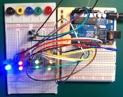
The time shown above is

10 +3 hours, 30 + 3 minutes or 13:33

The program for this is:

// binary clock

#define LED1M 2
#define LED2M 3
#define LED4M 4
#define LED8M 5

#define LED10M 6
#define LED20M 7
#define LED40M 8

#define LED1H 9
#define LED2H 10
#define LED4H 11
#define LED8H 12

#define LED10H A0
#define LED20H A1

#define MBUTTON A4
#define HBUTTON A5

static unsigned long tick;
int sec = 0;
int minu = 0;
int hr = 0;
int munit;
int hunit;
   
void setup()
{  
  pinMode(LED1M, OUTPUT);
  pinMode(LED2M, OUTPUT);
  pinMode(LED4M, OUTPUT);
  pinMode(LED8M, OUTPUT);
  
  pinMode(LED10M, OUTPUT);
  pinMode(LED20M, OUTPUT);
  pinMode(LED40M, OUTPUT);
                
  pinMode(LED1H, OUTPUT);
  pinMode(LED2H, OUTPUT);
  pinMode(LED4H, OUTPUT);
  pinMode(LED8H, OUTPUT);
  
  pinMode(LED10H, OUTPUT);
  pinMode(LED20H, OUTPUT);
  
  pinMode(MBUTTON, INPUT_PULLUP); // set minutes button
  pinMode(HBUTTON, INPUT_PULLUP); // set hours button
  
  tick = millis(); // start clock
  
}

void loop()
{
   
   if(millis() - tick >= 1000) // basic timing
   {
     tick = millis();
     sec++; // count seconds

   }
   
   if(sec >= 60)
   {
     minu++; // count minus
     sec = 0;

   }
   
   if(minu >= 60)
   {
     hr++; // count hrs
     minu = 0;
   }
   
   if(hr >= 24)
   {
     hr = 0; // reset hrs
     minu = 0; // and min
   }
   
   munit = minu%10; // get min units
   hunit = hr%10; // get hr units

   // convert 1st column to binary
   if(munit == 1 || munit == 3 || munit == 5 || munit == 7 || munit == 9) 
   {  
     digitalWrite(LED1M, HIGH);
   }
   else 
   {
     digitalWrite(LED1M,LOW);
   }
   if(munit == 2 || munit == 3 || munit == 6 || munit == 7) 
   {
     digitalWrite(LED2M, HIGH);
   }
   else 
   {
     digitalWrite(LED2M,LOW);
   }
   if(munit == 4 || munit == 5 || munit == 6 || munit == 7) 
   {
     digitalWrite(LED4M, HIGH);
   }
   else 
   {
     digitalWrite(LED4M,LOW);
   }
   if(munit == 8 || munit == 9)
   {
     digitalWrite(LED8M, HIGH);
   }
   else 
   {
     digitalWrite(LED8M,LOW);
   }
   
   // convert 2nd column to binary
   if((minu >= 10 && minu < 20) || (minu >= 30 && minu < 40) || (minu >= 50 && minu < 60))  
   {
     digitalWrite(LED10M, HIGH);
   } 
   else 
   {
     digitalWrite(LED10M,LOW);
   }
   if(minu >= 20 && minu < 40)  
   {
     digitalWrite(LED20M, HIGH);
   }
   else 
   {
     digitalWrite(LED20M,LOW);
   }
   if(minu >= 40 && minu < 60) 
   {
     digitalWrite(LED40M, HIGH);
   }
   else 
   {
     digitalWrite(LED40M,LOW);
   }

   // convert 3rd column to binary
   if(hunit == 1 || hunit == 3 || hunit == 5 || hunit == 7 || hunit == 9) 
   {
     digitalWrite(LED1H, HIGH);} 
   else 
   {
     digitalWrite(LED1H,LOW);
   }
   if(hunit == 2 || hunit == 3 || hunit == 6 || hunit == 7) 
   { 
     digitalWrite(LED2H, HIGH);
   } 
   else 
   {
     digitalWrite(LED2H,LOW);
   }
   if(hunit == 4 || hunit == 5 || hunit == 6 || hunit == 7) 
   {digitalWrite(LED4H, HIGH);
   } 
   else
   {
     digitalWrite(LED4H,LOW);
   }
   if(hunit == 8 || hunit == 9) 
   {
     digitalWrite(LED8H, HIGH);
   }
   else 
   {
     digitalWrite(LED8H,LOW);
   }

   // convert 4th column to binary
   if(hr >= 10 && hr < 20) 
   {
     digitalWrite(LED10H, HIGH);
   } 
   else 
   {
     digitalWrite(LED10H, LOW);
   }
   if(hr >= 20 && hr < 24)  
   {
     digitalWrite(LED20H, HIGH);
   } 
   else
   {
     digitalWrite(LED20H,LOW);
   }
   
   if(digitalRead(MBUTTON) == LOW)
   {
     minu++;
     sec = 0;
     delay(250); // allow for contact bounce?
   }
   
   if(digitalRead(HBUTTON) == LOW)
   {
     hr++;
     sec = 0;
     delay(250);
   }
}
   

Thursday 12 December 2013

LCD Temperature & Humidity

Next step, display the Temperature and Humidity on an LCD display. Like this:

2013 12 12 15 23 18

The circuit for this is:

2013 12 12 15 21 15

And the board layout is:

2013 12 12 15 23 04

The code has no error checking at this time::

#include "dht11.h"
#include "LiquidCrystal.h"


// LCD connections
#define RS 0
#define EN 1
#define D4 5
#define D5 4
#define D6 3
#define D7 2

// LCD mode
#define cols 16
#define rows 2

dht11 DHT11;
// sensor pin
#define DHT11PIN 12

LiquidCrystal lcd(RS, EN, D4, D5, D6, D7);

void setup()
{
  lcd.begin(cols, rows);
  delay(2000);
}

void loop()
{
  DHT11.read(DHT11PIN); // make a read to refresh the temp & humid
  
  lcd.clear();
  lcd.setCursor(0, 0);
  lcd.print("Humid (%) ");
  lcd.print((float)DHT11.humidity, 2); // humid 2 dec places


  lcd.setCursor(0, 1);
  lcd.print("Temp (C) ");
  lcd.print((float)DHT11.temperature, 2); // temp 2 dec places
   
  delay(2000);
}

Temperature & Humidity

Now here's a very neat device. A small unit that measures Temperature (degC) and Humidity (%) directly.

2013 12 12 13 07 36
Communication with the device is tricky, but there is an Arduino Library "dht11.h" which make the whole thing very simple. See Here. You have to copy the ".h" and ".cpp" files one by one to a text editor and save them. Then put them in your Arduino library folder in a sub folder called "dht11"

The connections are (S = Signal, Centre Pin = +5V, - = GND):

2013 12 12 13 09 50
The pull up resistor is essential, otherwise you get wrong readings...

Here's my test bed:

2013 12 12 13 08 12

And the display on the Serial Monoitor of the Arduino IDE:

Screen Shot 2013 12 12 at 13 05 34 The code

#include "dht11.h"

dht11 DHT11;

#define DHT11PIN 2

void setup()
{
  Serial.begin(9600);
  Serial.println("DHT11 TEST PROGRAM ");
  delay(2000);
}

void loop()
{
  Serial.println("\n");

  int chk = DHT11.read(DHT11PIN);

  Serial.print("Read sensor: ");
  switch (chk)
  {
    case DHTLIB_OK: 
		Serial.println("OK"); 
		break;
    case DHTLIB_ERROR_CHECKSUM: 
		Serial.println("Checksum error"); 
		break;
    case DHTLIB_ERROR_TIMEOUT: 
		Serial.println("Time out error"); 
		break;
    default: 
		Serial.println("Unknown error"); 
		break;
  }

  Serial.print("Humidity (%): ");
  Serial.println((float)DHT11.humidity, 2);

  Serial.print("Temperature (C): ");
  Serial.println((float)DHT11.temperature, 2);

  delay(2000);
}