WORK IN PROGRESS
I am at the thinking stage and fiddling about stage, I have been inspired by the keithSDR project and N6QW to work out my own Teensy based SDR Transceiver.
Hardware
The hardware is made up of
- a QRP Labs SDR receiver module, covering 1-30MHz. Synthesiser input @ x4 frequency, output Audio IQ to
- a Teensy and Audio Adapter, and connected display, encoder, PTT switch, band & sideband buttons, SWR bridge inputs
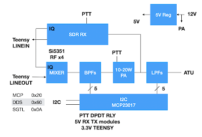
- a home grown RF & AF IQ mixer, a set of BPFs, a QRP Labs 10W PA and a set of LPF, covering 5 bands 80-40-30-20-15. This will be the most difficult part of the project, why doesn't someone make a module for this?
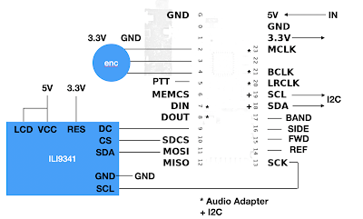
Teensy 4.0 connections
RF block diagram, plus an SWR bridge...
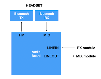
Audio adapter, can I do Bluetooth audio to a headset.
a huge software challenge?
Self developed SSB RF generation
Tough!
Controlling the SDR are
- a PTT DPDT switch or relay (5V for RX & PA, 3.3V for Teensy PTT)
- a Band select button
- a USB/LSB sideband button
- a rotary encoder for Tuning
- a frequency tuning step button (on encoder)
with an 2.8" or 3.5" TFT colour display (ILI9341 or ILI9488)
One thing that has not, yet, been thought about is CAT control of the transceiver. If I do it I will chose the more simple Kenwood ASCII command approach.
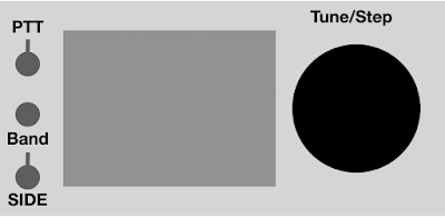
Dream layout KISS
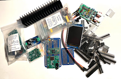
Starting to gather the parts
10W PA, RX, Display, relay kit, 5V PSU, Teensy & Audio board, headers
SWR Bridge
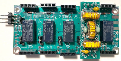
Make the easy things first
One of the two QRP Labs modules (Mixer BPF & PA LPF) , here with a 20m LPF mounted
LPF module, sockets are not as
wobbly as this photo seems to show!
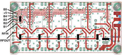
Connections, using 2 x 5 pin header for B1 to B5 & +5
Links shown in solid black
I will need to build some BPFs as I want to design the RF IQ mixer first, then probably the display layout next so I will need the Teensy. In the mean time I want to try out the PA with my QCX to push up the power on WSPR...
The QRP Labs 10W PA
In build
Teensy & Audio Adaptor
In development.
My T4 does not work - may have blown it up, electrostatics? Playing with T3.2 for screen function developments (see below). I also will need a new audio adapter, T4 if I replace it or T3.2 if not...
Power supplies
A small 12V/3A SMPS and a 5V regulator, 3.3V comes from the Teensy. May put 12V outside and only 5V reg internally...
Power supply 12V/3A and 5V regulator
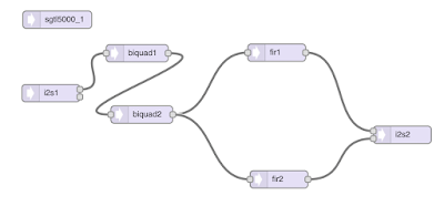
Software
The basic processing plan is this - a simple solution I admit, for now.
TX
RX
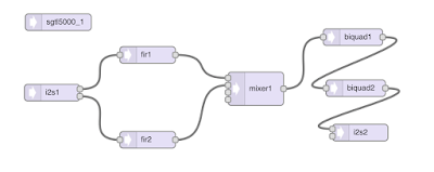
In both chains there are two Hilbert audio BPF with +45 and -45 deg phase shifts, and two Biquad filters of 300-2.3kHz to sharpen up the overall filtering. Choice of sideband is made by software swapping Hilbert +45 and -45 in the chains. I hope to use 96kHz audio BW, may have to modify the RX. How do I get the audio adapter SGTL5000 to run at 96kHz rather than 44.1kHz???
PTT will switch the audio configurations above, and also chose the input/output configuration. On TX MIC & LINEOUT, on RX LINEIN & HP OUT. Sideband switch will swap the Taps +/-45 of the FIR filters. The frequency is handled by an interrupt routine from the rotary encoder, and the frequency step is a button input, as is the band/start frequency.
These audio components and pathways are defined using the new Open Audio F32 library (a 32 bit floating point audio library for the Teensy). An S meter will show the rms signals and if am clever the peak also, and an FFT will display a spectrum and water fall over a range +/-48kHz of the centre frequency.
Screen layout
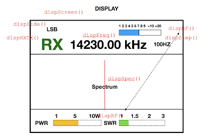
This is my first proposal, fairly simple with the functions currently being written to handle each part shown. I plan to use a low cost ILI9341 2.8" or 3.5" screen.
Proposed display
The basic underlying layout is initialised by "dispScreen()" and the items are displayed by dedicated functions. Not that "dispRF()" handles all three of Power, SWR and S meter bar charts. Others are
- dispRxTx(ptt), for the large RX or TX signs
- dispSide(side), for the USB/LSB sideband
- dispStep(freqStep), for the tuning step 10Hz - 10kHz
- dispFreq(freq), for the frequency in kHz - updated by encoder interrupt
- dispSpec(?input), for the spectrum - free running
- dispRF(SLevel, power, swr), for the S meter (RX), power and SWR meters (TX) - free running
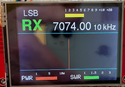
Here's the current screen
Draft screen layout
Trial on Teensy 3.2
A test display sketch using Adafruit GFX library and Adafruit ILI9341 driver works on an Arduino UNO, but it is very slow to update the display. It also works on a Teensy 3.2 much faster. I will continue development for the Teensy 3.2 which I have previously used as a stand alone IQ SSB decoder with an Elektor SDR RF front end. And look to moving to the Teensy 4.0 later.
Test sketch MYSDR_TEST and Tft.h Header
As far as the arrangement of the software is concerned. I have followed my previous style and am putting most of the detail functions (dispFreq() etc) in a separate Tft.h header file and the SDR funcitons (setPtt() etc) in a separate Sdr.h header. This much simplifies the main sketch code. Current MYSDR_TEST and Tft.h can be found
here, but updates are quite frequent.


1 comment:
Thank you for this resource!Very inspiring investigations of SDR. I am making baby steps. Mentioned this blog in one of my videos as it is absolute technical treasure. 73 de Vk2AOE. George
https://youtu.be/qdgN9XR5mz0
Post a Comment