Thursday, 31 December 2020

Building a QCX+ CW transceiver

I have ordered a QCX+ transceiver from QRP-LABS.  But before it arrives I decided to take a look at the RX circuit, This is in three parts

1. A basic Tayloe quadrature detector, fed by RF signals with 0/90deg phase shift from a programmed Si5351 synthesiser. (See here for an example Arduino program snippet on how to do it)

The QCX+ RX frequency is set 700Hz lower than the TX frequency to give a 700Hz beat. This uses the Upper Side Band for reception. The VFO A display always shows the higher TX frequency.

2. An AF phase shift network, tuned to have a 0/90deg phase shift at a narrow band of audio frequencies, nominally around 700Hz +/- 100Hz.

3. An AF filter with a peak response at 600-800 Hz.

1. DETECTOR

Some info about generating 0/90 deg phase shift RF I & Q signals is in my blog in Digital SSB, April 2020 posting. With an Arduino code listing for this type of application here. I think QRP LABS have published their "Arduino" code for the QCX+ also. 

More info about SDRs and the Tayloe detector is here (pdf)

2. PHASE SHIFT NETWORK

To be analysed. But its very simple and only splits the 0 & 90deg I & Q signals over a narrow band of audio frequencies, no good for SSB reception...

3. BAND PASS FILTER

The first discussion and LTSpice simulation is of #3,, the audio filter. The result (pdf) and spice (".asc" file) are here. As you can see this is an effective CW filter at the popular listening AF of 600-800Hz. The actual audio frequency, which is simply the TX-RX offset frequency can be set in a menu item, but of course must lie in the BW of the hardware filter!


MENUs - here is a summary of the menu.

QCX MENUs


SELECT___


1 Preset S

   1.1 - 1.16 freq presets


2. Messages S

   2.1 send interval

   2.2 reeats

   2.3 - 2.14 messages


3. VFO S

   3.1 mode A, B, SPLIT

   3.2 VFO A default

   3.3 VFO B default

   3.4 Tune rate default

   3.5 RIT default

   3.6 RIT rate default

   3.7 CW-R ON|OFF mode, OFF RX is USB

         TX-OFFSET, ON RX is LSB TX+OFFSET

   3.8 CW OFFSET nom. 700Hz


4. Keyer S

   4.1 straight, IAMBIC A, IAMBIC B, Ultimatic

   4.2 keyer speed WPM

   4.3 keyer swap dit/dah ON|OFF

   4.4 keyer weight, 500 = 1 dit, 3 dah, 7 word

   4.5 auto-space ON|OFF 3xdit between chars

   4.6 semi QSK ON = semi-QSK

         OFF = full QSK break-in

   4.7 practice ON = no TX, OFF = TX

   4.8 sidetone Hz nom 700Hz

   4.9 sidetone vol

   4.10 straight mode TIP, RING, BOTH 

        3.5mm connections


5. Decoder S

   5.1 Noise blanker (ms)

   5.2 speed avg

   5.3 amplitude threshold 

   5.4 enable RX decode ON|OFF

   5.5 Enable TX decode ON|OFF

   5.6 enable edit ON|OFF - key entry of msgs

   5.7 VA/SK display ON|OFF


6. Beacon S

   6.1 mode OFF, CW, WSPR, FSKCW (QRSS)

   EXIT_ = STOP

   6.2 Frequency TX freq 7040000 - 7040200

   6.3 frame WSPR repetition rate WSPR (min)

   6.4 start time past hour

   6.5 WSPR call _M0IFA (6 char)

   6.6.WSPR locator IO92, or set by GPS

   6.7 WSPR power (dBm) 5W = 37dBm

   6.8 set time RTC, or set by GPS


7. Other S

   7.1 double click sets button press timing (ms)

   7.2 battery ON|OFF display voltage icon

   7.3 battery full detect level nom. 13,800 mV

   7.4 battery step nom 1,000mV/bar

   7.5 cursor blink ON|OFF

   7.6 S-meter ON|OFF display

   7.7 S-meter step nom 100, sets sensitivity

   7.8 custom splash set own power-up screen

         from messages 11 & 12

   7.9 clock ON|OFF display

   7.10 delimiter char nom “,”

   7.11 factory reset sure? rotate to 17


8. Alignment S

   8.1 align frequency set to centre of CW band

   8.2 I-Q balance frequency phase shift at 700Hz

   8.3 phase low frequency phase shift 600Hz

   8.4 phase high frequency phase shift 800Hz

   8.5 reference frequency 

         27,004,000 Hz Si5351 clock (GPS cal)

   8.6 system frequency

         20,000,000 MCU clock (GPS set)

   8.7 peak BPF, audio amplitude at 700Hz

   8.8 I-Q balance reference frequency 700Hz

         to unwanted sideband (LSB)

   8.9 phase low —ditto - 600Hz

   8.10 phase high — ditto— 800Hz

   8.11 calibrate reference oscillator,

           activate GPS calibration, waiting, 6sec

           3-2-1 closer calibration

           0 OK calibrated

   8.12 calibrate system oscillator,

           —ditto—


9. Test equipment S

   9.1 DVM input 0-20V nominally, jumpered 

         to battery voltage

   9.2 RF power 0-5W

   9.3 audio ch 1, audio amp input

   9.4 audio ch2, phase null output

   9.5 frequency of counter input to

         timer 1 of MCU (5Vmax) 

   9.6 signal generator CLK0&1 3.5kHz to 200MHz


Save settings (to EEPROM) S


EXIT_

Monday, 14 December 2020

Mac Mini setup for SDR FDM-SW2 (Windows) and WSJT (MacOS)

I am running the ELAD FDM-SW2 SDR software under Parallels and Windows 10 on my Mac Mini, 

FDM-SW2 under Parallels & Windows 10

This is the setup I have for signal routing to get everything to where it is supposed to be. I have connected all three USB connection on the FDM-DUO to the Mac Mini. 

SOUNDSOURCE

I am using SoundSource  to direct the sound coming from FDM-SW2 through Parallels to a Bluetooth LS.


In this way the specific audio output of Parallels is directed to the Bluetooth "Anker Soundcore" LS. (the BT connection has to be "Connect" in MacOS for this, of course).

WINDOWS 10

Next we have to set up FDM-SW2 SDR software running under windows. We need not only to set up the audio, but also switch one of the USB inputs to Windows. This is the FDM-DUO "RX" connection to deliver the SDR IQ data. This can be done in the Widows 10 desktop by using the Parallels tools, opened by sliding the cursor to the top of the window.


Select the USB Icon and chose the FDMDUO USB FW v4.9 connection to Windows. FDMDUO has an odd naming convention for its USB connections, they correspond to

- FDM-DUO Audio v1.04 = TX connector, audio IN and OUT digital 48kHz
- FDMDUO USB FW v4.9 = RX connector, for FDM-SW2 software
- FT232R USB UART = CAT connector , ASCII commands IN and OUT for CAT control

why ELAD can't name them sensibly is a puzzle for another day.

PARALLELS

Parallels is set up to send its audio to "Default" as it is captured and re-directed by SoundSource (above). 


FDM-SW2

In FDM-SW2 chose "SET" and the Audio tab, and chose Soundcard and output device "Speakers (High Definition Audio)" which is what Parallels calls its audio output


WSJT

WSJT on a MacOS desktop

To run WSJT at the same time but under MacOS, Open it in a new desktop and  under WSJT > Preferences chose the Audio tab and set a direct connection to the USB audio to/from the FDM-DUO TX connection (it is not only TX input as the marking would suggest, but also RX digital audio output!)

SO...

After all that, phew! You can use WSJT and FDM-SW2 SDR at the same time. Both programs will issue CAT commands, if you set the frequency in WSJT to for example 7074.0kHZ for 40m, then the central frequency of the FDM-DUO is set to this and this is what FDM-SW2 display shows as the RED frequency (it will also set it to Upper Side Band). Use the yellow, green or blue receivers set to LSB to transmit SSB on the lower bands.

SSB TX

To transmit on SSB you must set up the FDM-DUO to accept USB or MIC audio input by Menu 32 TXIN set to AUTO. Then PTT will trigger with the microphone as usual. WSJT will also PTT using RTS signal on the CAT connection.

AND THE BEST BIT, AND THE WORST BIT

Funneling the output audio through SoundSource has a big advantage. Voice communications occur in a narrow band of audio frequencies based around 500-2500Hz. SoundSource has the ability to apply audio filters to any application channel. And this can be used to filter the output of Parallels to the Bluetooth speaker using a 10 band EQ. This makes a dramatic difference to the capture of weak voice signals! I am testing if the same routing can be done for an externally connected microphone feeding audio into Parallels an don to FDM-SW2 on transmit...


Of course FDM-SW2 has also an audio processor with EQ, VOX and Compression for trasnsmit, would that was easier to setup and use!!! It can take its input from a USB or normal microphone plugged into the Mac Mini. And feed its output to the TX digital input of the FDM-DUO radio via the TX input. But then you cannot use TX & CAT for WSJT FT8... sigh.

Even on a pure Windows setup getting WSJT to work is a mess of different softwares needed to redirect the audio to/from FDM-SW2 and the CAT control from WSJT... not a pretty site.

Saturday, 12 December 2020

Another go at WSPR

 I thought to pass the time I would have another go at WSPR. I have a simple Arduino sketch WSPR_FIXED written to program an Si5351 synthesiser to transmit WSPR on 7040.1kHz (1500Hz audio from an RX tuned to 7038.6kHz). I have also a very simple two transistor RF amplifier which can generate 0.5-1W output.

I tested it using my ELAD FDM-DUO receiver, coupled to my Mac Mini running WSJT software.

However the output of to Si5351 CLK1 is much to large to connect to the amplifier input! So in an odd way I must use a -30dB attenuator, then amplify it back up! Here's the scheme of things

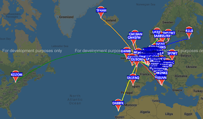
I am using my regular small 60cm loop antenna (simply because no outdoor antenna are permitted at my QTH). And here is what I got in the last 24 hours (from WSPRnet site)


I call that pretty much amazing for 500mW and the small loop antenna. Toronto, Iceland, Canaries, St Petersburg!!!

Sunday, 6 December 2020

Pixie challenge

 A couple of years ago I ran a light-hearted challenge at our radio club. Called the "Pixie Challenge". 

The Challenge

I sourced and provided a kit of pieces including the famous Pixie CW transceiver (fixed 7023kHz), all the plugs and sockets and a small audio amplifier/speaker.

The kit.
The challenge was in two parts:

1. Build the Pixie kit and get it working. To prove this club members had to receive a CW Beacon transmitted from my programmable VFO - an Arduino Nona and a Si5351 synthesiser (See here) which was transmitting "CQ PIXIE K" at 10 words per minute. (CW_BEACON Arduino code here)

2. Make a CW QSO between two Pixies, passing a secret code  known only to each individual.

This was the set up showing the programmed VFO and the Pixie


Ironically the prize, a soldering iron, was won by a new, non-licenced member of the club! But the most experienced "old boy" ruined his kit by soldering the transistors in backwards.


Saturday, 21 November 2020

New computer setup

 As I mentioned a couple of posts ago my old iMac failed. My son has given me his Mac mini - thank you.

I have purchased a superb 15.6" 16:9 screen and a new Apple keyboard. Both are amazing. Here's my setup now


Currently running Windows 10 under Parallels, and ELAD FDM-SW2 connected to my ELAD FDM-DUO transceiver. As well as, on a 2nd desktop, WSJT-X running under MAC OS.

Whopee, back in business.

Wednesday, 18 November 2020

More Mac Big Sur chaos WSPR

So WSJT-X does not work on OS 11, Big Sur. It returns the famous Memory Error. WSJT-X uses a shared section of memory to swap data between its waterfall and the control windows. On previous versions of Mac OS (e.g. Catalina) the standard OS amount of shared memory was about 7MB, but WSJT-X needed 14MB.

The shared memory could be increased by changing the memory size in a file called /etc/sysctl.conf. But on Mac Big Sur this file is no longer present! And so far I have not discovered what replaces it. (Never fear, see below)

I guess eventually the WSJT-X development group will solve the issue, but until then I will use my Mac Mini which still runs Mac OS Catalina and runs WSJT-X perfectly. As well as Parallels to run Windows programs.

====

See a later blog post for an installation solution that worked for me


Tuesday, 10 November 2020

iMac HDD failure

 Whoops. All of a sudden Mac OS Catalina fails and crashes on my rather old (2012) iMac. Oh dear.

First I decide to try re-formatting ("Erasing") the HDD, this fails. I try again using an older file format, and it works. So I re-install the original OS Mountain Lion and this runs, but any attempt to upgrade to the latest Catalina fails (Catalina partitions the HDD into Programs & Data, I guess this doesn't work...))

Off to the Apple store and get a test. This reports that the HDD has indeed failed on one sector. They suggest I can recycle the iMac (offering a miserable £100) and they tell me the computer is too old to repair - they have no HDDs to put in it!

This is all very sad. Until my son offers to give me a 2015 Mac Mini he has but is not using - the kids were using it for school work - mostly in Microsoft Word etc. But he has no Key Board nor a screen display spare to offer with it. I shout whoopee for he has upgraded the RAM to 16GB and put in a 256Gb SSD which has speeded it up enormously.

So now I have to solve a couple of problems

1. Access the machine to sort it out, basically erase everything and install Catalina and set it up with my name and iCloud address. To do this I wire it up HDMI to my living room TV! And use the old iMac keyboard and mouse. It works a treat. I return the iMac for recycling.

2. Meanwhile I source a screen and use the £100 they will give me for my old iMac to buy a new keyboard (I have a spare Track Pad). I purchase a 15.6" screen on eBay, it arrives broken and I am struggling with the supplier to replace it or give me my money back... we will see.

But in the mean time I have configured the new Mac Mini to allow screen sharing and can access it very easily from my MacBook over wifi. So that is what I am  doing. And making lots of FT8 QSO with WSJT installed.

Later

Days later I purchase a "very" expensive 15.6" screen, which is luxury and perfect with a 16:9 ratio & HDMI interface. I am very pleased with it.


Wish me luck.


Wednesday, 30 September 2020

My Small Shack

My shack is small and ALL indoors. The antenna is a small 60cm loop a-top an Auto ATU here:

You wouldn't think with my 5W you could get far with that, would you? But I enjoy my contacts using digital FT8 mode, especially on 20m. This is the rest of my shack, first the big picture:

Left to right, GPS clock, iMac, MacBook, FDM-DUO and 13.8V PSU

The GPS clock has been described in this blog below, it runs beautifully, but I have not yet boxed it up... The old iMac is a bit on the slow side, but runs WSJT, Grid Tracker and displays my log file. Underneath the iMac is a low cost Android tablet running ELAD Blueduo app. This gets spectrum and CAT data from the FDM-DUO transceiver via a small Bluetooth dongle and displays it. Next is the MacBook running Parallels and Windows 10, and then running the ELAD FDM-SW2 SDR suite. Lastly is the FDM-DUO transceiver itself with a home made 13.8V power supply, also described in this blog.

And here is the iMac running WSJT for FT8 mode:

iMac running WSJT

And the MacBook running Parallels, W10 & FDM-SW2, zoomed in on 14074kHz FT8 signals.

MacBook running Parallels, W10 & FDM-SW2

The FDM-DUO transceiver - an elegant, very small, very hi-tech SDR. With amazing performance, an almost entirely digital radio. But low powered at 5W output.

On the left a Bluetooth dongle to communicate with 
the Android tablet running Blueduo app.

The Android tablet running Blueduo app. Displays the spectrum and waterfall, and is able to control the FDM-DUO by CAT commands. 

Android tablet running Blueduo.

And that is it. Latest conquests, W. Sahara and Cyprus. That's DX for me!

Monday, 28 September 2020

Extensive Arduino course

Note: all files and sketches on M0IFA.me

For beginners or to catch up. M0IFA.me has a full Arduino course, with course notes and all the sketches you need. I suggest you use this starter kit, it has all the pieces you need.

The kit is available from here. But add an LCD I2C interface here.

Please use it, copy it, distribute it. All free of charge!

Monday, 21 September 2020

E-paper weather monitor

Weather does not change very quickly, so it is one of the things that can be displayed on a e-paper display which cannot be updated on the fly, but only as the whole screen at a time.

There is a product called DHT11 on the market which measures temperature and humidity, from which you can calculate the dew point.

These are easily used in an Arduino sketch with a library called dht11.h (download here). This is the project


Sketch EPD_TEMP is here. You also need the updated epda.h header here, put it in your libraries folder. 

Good for SOTA activations and field days!

Monday, 14 September 2020

Web Site audio in Apple Safari

 I came across G4FPH's WebSDR site. It worked well, but there was no audio from the Apple Safari browser... I have met this issue before on other web sites.

G4FPH website

It seems that Safari controls audio for each web site you visit. To get it to work follow these steps

- Open Safari & the WebSDR site

- Chose Safari menu

- Chose Settings for this Website...

- in the small window that opens chose Auto-play and select Allow All Auto-Play

And presto, sound.

Sunday, 13 September 2020

Climate Emergency - seriously

Apart from my interest in Amateur Radio, I have another side (wow). A focus on what to do about the climate emergency. One of the major areas which I feel  we must address is transport - namely road transport. CO2 emissions from transport are going up, not down. In 2021 all makers must meet the level of 95g/km overall... or be fined HUGE amounts.

But some good news is the sales of BEV (Battery Electric vehicles).

 I have put on my download site (M0IFA.me) a collection of snippets "EV POLITICAL ..." about transport and electric vehicles, here.

And I invite you to read this report by The Institute for Government.

Friday, 4 September 2020

GPS clock, colour 2.4" TFT display

Note: all files and sketches on M0IFA.me

What a struggle! These TFT displays are awkward to use. Especially when you want to display a clock face and hands that move round, or for that matter to write text/numbers on the display and update them. To move a hand you must delete the previous line you have drawn and draw a new one. BUT, you cannot let the second hand, as it moves round, delete the minute or hour hand as it passes by...

Same for the time. When the hours, minutes or seconds change you have to write a black box over the original number and then the new time. Fortunately the simple Adafruit font does this by allowing you to define both the font colour and the background colour. The negative side of using the simple font is that it is very blocky and only small sizes can be used.

MY CLOCK

This is my display. This TFT has 5V operation and I am running it quite happily on the Arduino Mega at 5V.

The display is complete after I added a calculation of
day of the week and the Maidenhead Locator.

The TFT has an ILI9341 controller chip. This is supported by the Adafruit_GFX.h library with the driver Adafruit_ILI9341.h. This graphic library is not very extensive, but does have to simple things I needed, filled rectangles, circles, horizontal and vertical lines, sloping lines, print of numbers and text.

The interesting code for the clock hands is this:

 - x, y = centre of hands

 - r = radius of clock

 - ch, h etc are the colours and hour, min, sec values

Typical usage may be

dispHands(110, 110, 100, WHITE, hrs, WHITE, mns, RED, sec);

This is the function:

// HANDS

// display hands x, y, r, ch, h, cm, m, cs, s

void dispHands(int16_t x, int16_t y, int16_t r, uint16_t ch, uint8_t h, uint16_t cm, uint8_t m,  uint16_t cs, uint8_t s) {

 uint16_t rh, rm, rs; // hand lengths

 static uint8_t xh, xm, xs; // prev hms data


  // hand lengths, % of radius

  rh = r * 60/100;

  rm = r * 80/100;

  rs = r * 90/100;


  // proportional move of hour hand

  h = h * 5 + m / 12.0; // 60 min / 12 hours, plus minutes / 12


  // if hms change erase old hand

  if (h != xh) {

  tft.drawLine(x, y, x + rh * sin((6.282 * xh / 60.0)), y - rh * cos((6.282 * xh /60.0)), BLACK);}

  if (m != xm) {

  tft.drawLine(x, y, x + rm * sin((6.282 * xm / 60.0)), y - rm * cos((6.282 * xm / 60.0)), BLACK);}

  if (s != xs) {

  tft.drawLine(x, y, x + rs * sin((6.282 * xs / 60.0)), y - rs * cos((6.282 * xs / 60.0)), BLACK);}


  // then draw current times

  tft.drawLine(x, y, x + rh * sin((6.282 * h / 60.0)), y - rh * cos((6.282 * h / 60.0)), ch);

  tft.drawLine(x, y, x + rm * sin((6.282 * m / 60.0)), y - rm * cos((6.282 * m / 60.0)), cm);

  tft.drawLine(x, y, x + rs * sin((6.282 * s / 60.0)), y - rs * cos((6.282 * s / 60.0)), cs);


  // remember current time

  xh = h;

  xm = m;

  xs = s;

}

Just to run though it

1. Three static variables for hour, minute & second are created in the function, these are remembered between calls. They store the "previous" values.
2. The length of the hands is set as 60, 80, 90% or the radius.
3. Hours are converted to 60ths and intermediate minutes added, so the hour hand slowly goes round with the minutes
4. A check is made to see if anything has been updated, if so the old hand is erased (written over in BLACK colour)
5. The new hands are written. All of them MUST be written as an erase of the secondhand as it passes over the minute of hour hand will "black" it out!
6. Finally the current values are stored for the next call.

All the date & time and display functions have been written in a "Tft.h" header file, here. And the sketch code TFT_ADA_MEGA.ino is here. Name started off as "TFT using Adafruit" library, but it stuck.

TIME
So where does the time come from? GPS of course, and this is relatively easy to do using a GPS module and the TinyGPS library. See the sketch for the code.

Here it is running on an Arduino Mega
Display: CLK 13, MOSI 11, RES 8, DC 9, [CS 10, MISO 12 not used]
GPS: RX 18, TX 19

UNO or NANO
The clock will work equally well using an UNO or NANO. But here you will have to implement the serial port for the GPS in software using the SoftwareSerial library, part of the Arduino IDE installation. The sketch is TFT_ADA_NANO, shown working on the UNO as I don't have a spare Nano around at the moment...


The display has a bit of a lag as the UNO (and NANO) are slower than the MEGA that I originally used.

QSO

The project has obvious use in the Amateur Radio shack for logging QSOs and checking the timing of transmissions - including for example FT8 which must start +/- 1 sec from the 15 seconds boundaries.


Wednesday, 2 September 2020

More on Digital SSB generation

 If you look back through this blog you will see (June 2020) a couple of reports of me delving into generating SSB signals using the digital "Phasing Method" using a Teensy processor to do the DSP processing using a couple of Hilbert filters. Hilberts give a band pass characteristic, plus they can be programmed to provide a signal phase shift. The design uses a +45 and -45 deg phase shift to generate I & Q audio signals, which are them fed to a couple of balanced mixers with RF I & Q signals. The result is USB or LSB SSB signals.

The SSB generator. Left Si5351 RF I & Q signals
Centre mixers and audio amp
Right the Teensy processor and mic input

It worked but it had a problem with the Hilbert filters, as they were limited to 70 to 100 taps, the Teensy could not handle a longer filter. This in turn caused the phase shift to move away from 45 deg at low AF frequencies. This then generated opposite sideband break though.

To tackle this I have added a couple of further processing steps. The Teensy processor is mounted on an audio ADC/DAC board and this can provide some audio preprocessing by itself. I have programmed it to provide an EQ with a passband of 500Hz to 3kHz and also an auto volume control, or compressor function. This is the code snippet

  soundcard.audioPreProcessorEnable(); // preprocess -3dB 500-3000kHz

  soundcard.eqBands(1.0, -1.0);

  soundcard.autoVolumeEnable();

  soundcard.autoVolumeControl(0, 1, 1, -10, 0.1, 0.1);

The full code for the app is on my website M0IFA.me here, it is called TEENSY_TX_ABPF.

On a listening test I found a significant improvement in the SSB punch and a reduction on the other sideband and correct side band audio BW.


Sunday, 30 August 2020

GPS QSO aid, Position & Time and Clock

I have been busy. It has always seemed to me that a GPS could be useful in the shack and in the field, So I have developed a very simple piece of hardware and a sketch to give 3 views of GPS data.

A GPS receiver can give you, amongst other things, the date, the time and your position in latitude and longitude. These things can be useful to the radio amateur, date and time for logging QSOs, and lat & lon translated to Maidenhead Locator for your stations position. 

I have chosen to display 3 different views, like this

The first is a display for QSO use, the second the raw GPS data and the third a conventional clock. All times are in UTC as this is GPS basic time.

BLOCK DIAGRAM / CONNECTIONS

After this digram was drawn I added a three way toggle switch connected to UNO pins A2 - GND - A3. This selects the type of display to show on the OLED display.

SOFTWARE
The software needed for this project is on my web site M0IFA.me.

1. The sketch itself is called GPS_HAM, copy and paste it into a new Arduino sketch and save with this name.
2. An Oled header file which gives the initialisation and  a set of functions based on the public u8g2 library for displaying text, numbers, clock hands, dates and times (and lots more if you need them). Put this is a folder called Oled in your libraries folder
3. The u8g2 library, which you can download from the internet, or copy from my site libraries
4. The Arduino SoftwareSerial and TinyGPS libraries which, again, you can download from my libraries.

Put Oled, SoftwareSerial and TinyGPS in their own folders in your local "libraries" folder.

BOX IT
I have ordered a small plastic box in which I will mount an Arduino Nano (replacing the development UNO I used), the GPS antenna and NEO-7 module and the OLED display. It will be powered from a 12V supply to the Nano which will them power the OLED and GPS.


Saturday, 22 August 2020

Time to tidy up our SSB transmissions

I have been astounded at the quality of SSB transmissions that are revealed by today's SDR receivers which show both a waterfall and a band spectrum. These are as seen on Hack Green SDR WEB receiver.

When I focused in on different transmissions I find

1. GOOD MODULATION

Beautiful, clear, full audio bandwidth, excellent audio processing.

2.  VERY BAD SPLATTER, PROBABLY DUE TO OVER MODULATION

Very poor and over modulated transmissions two on both sides and one on one side only. These transmissions often received reports of "good audio" which just shows that the quality of SSB transmission cannot be judged by just listening.

And it can't get worse than this

Just as he said "thanks for the report on good audio". Report "no audio artifacts", needs to use an SDR.

3. BOGGLED TRANSMISSIONS


This is about the worst in terms of quality. Patchy audio EQ, severely bass heavy and muffled and an outstanding transmission of a faulty transmitter or a wrongly used audio processor, giving a transmission of more than 9kHz wide!! This gentleman received a report of "clear, good audio"!!!

Then check this out. Two guys talking about "I like to focus on audio..." Here's the same guy again at 9kHz wide and severley distorted at the top end.


SDR BW is 3kHz, so top one is 4-5kHz wide and the bottom one more than 9kHz!!!

AND ACROSS 80M 


Very mixed quality of signals. Lot of audio processing and poor/good microphones?

NEW CODES NEEDED

The regular reports of 5 and 9 are not good enough. We need a better reporting system - a bit like SSTV which reports 5 & 9 plus video quality.

Tuesday, 18 August 2020

Remarkable WSPR results

 I know a lot of you will get spectacular WSPR reports. But for me this is remarkable


20 meters last 12 hours overnight

It is remarkable because I have only a small, low cost 60cm loop antenna, indoors, attached directly to the back of my SDR (ELAD FDM-DUO) and it is set to 4W output!

WSPR is a truly incredible signaling system.


OTA updates for radios

RADIOS ARE ALL SOFTWARE, THESE DAYS

For years it seems our computers have been support by "pushed" software updates. Be it a smooth Apple Mac update or a clunky and intrusive Windows update. Over The Air updates of both operating systems and applications are almost universal amongst professional OS and software sellers.

OK, so commercial forces do come into play. You may simply get an email saying a new version of the software is available, pay up to get it - couple of clicks and PayPal does the trick! Or on the other hand you may simply wake up one morning to a small notification on your Mac's desktop saying, new xyz has been installed while you slept or in the worst case "Restart to install" for a new version of the MacOS.

Whatever software vendors care about you and support their products with easy updates.

NOT SO, RADIOS

But for our radios that depend more and more on complex software, nothing. No updates. No emails. You have to search the vendor webs sites or be on a news group to find out that your version of the DSP  software has been upgraded. Then it is an almost impossible task to download it and install it in your radio - and if it goes wrong and you end up with a brick, then the only solution is to send it back for repair, and pay.

As ELAD, makers of my excellent FDM_DUO SDR said, the radio has no WiFi interface and we have no plans for it. Oh, come on. What does it take to install an ESP32 WiFi chip in a radio of this inherent almost 100% digital complexity? Nothing but a management decision. And proper customer support.

MAKERS wake up

This is simply not good enough. All major vendors of radios need to develop a service which goes along with their products that automatically and freely keeps them up to date and performing at their best. You pay a lot of money for a new radio these days - thousands of pounds - and this must include software updates that are transparent and automatic.

ICOM EXAMPLE

This is what ICOM says you have to do, clunky or what?

"To update the firmware 

• An SD card or an SDHC card is required. 
• Format the card in the IC-7300 before using it for the update. (First, save any data that is on the card, if necessary.) 
• Unzip and save the downloaded firmware file in the“IC-7300" folder that is on the card. 
• Save the transceiver’s data onto a separate card before the update, as it is possible that your data could get lost or corrupted during the process. Thoroughly read Section 8 (USING AN SD CARD) in the FULL MANUAL for details. 
• Thoroughly read Section 15 (UPDATING THE FIRMWARE) in the FULL MANUAL before starting the update. 
• Never turn OFF the transceiver power during the update. "

AND YEASU?

"Caution!
Please be sure to confirm the model and the version of your transceiver before starting the update. Writing incorrect firmware to the transceiver may cause abnormal operation or failure. Do not install this version firmware to any FT1XDR/DE. The update firmware is NOT compatible between FT1DR/DE and FT1XDR/DE.

Refer to the firmware update procedure instructions in the help files (.pdf files) inside the ZIP folders.

Refer to the firmware Update Instruction Manual in each ZIP file."

How terrifying is that???

Friday, 7 August 2020

ELAD Blueduo

BLUEDUO - remote operation of the FDMDUO SDR 

One of the programmers of the ELAD FDM_DUO SDR has worked with ELAD to create a very interesting application. This is called BLUEDUO and is a bluetooth connection to the  SDR which allows remote working. The only thing it does not provide is remote sound in or out... which I guess is due to the comms speed of Bluetooth being to low to handle both the tuning and spectrum data as well as audio.

The Blueduo software is a Google Android app available on the ELAD web site. To try it out I have

1. Begged and borrowed an Android tablet from my son - who has everything

2. Purchased a Bluetooth dongle, HC-05

3. Used a FT323 USB <-> Serial TX, RX dongle I already have to program the HC-05

4. Downloaded the software "apk" file from ELAD, and installed this on the tablet - for this you need to download it, use the tablet file manager and give permissions under settings to allow non-Google Play Store apps to be installed. But then it is just a matter to double clicking the downloaded file to install it.

5. Bought a DB9 male plug to connectors flat cable (There may be other sources, it was very difficult to find!)

BUT FIRST, PROGRAMMING THE HC-05

The FT232 pins connect to the HC-05 as follows

FT232  HC-05

GND -> GND

VCC -> VCC

RXD -> TXD

TXD -> RXD

The HC-05 has now to be programmed. Wire it up as listed above. 

When delivered the HC-05 dongles almost certainly come with their baud rate set to 9600 or 38400 baud. Connect the FT232 by USB to your computer - mine is an Apple MacBook. I use a serial terminal app called iSerialTerm which can select the USB port, select the speed 38400 and start a connection (There will be Windows terminal apps, but I don't know about them). Set the "Send" format to be your typed commands followed by a CR/LF (/r/n).

But first disconnect the HC-05 Vcc, press the small button and hold it down, then reconnect the Vcc to get into program mode. Showed as a slow flashing LED. 

Now check the HC-05 is responding by sending a command.

AT+VERSION?

to which it should respond with its version number. 

When you have a correct response enter the following commands - you may have to repeat entry to the program mode before each command is given - I did...

AT+NAME = BLUEDUO

AT+UART = 115200,0,0

AT+PSWD = 1234

This will set the Bluetooth dongle name to BLUEDUO, to a speed of 115200 baud required by the FDM-DUO and a Bluetooth password of 1234.

WIRE UP THE HC-05

Now you can remove the FT232 connections and make connections to the 9pin connector of the FD-DUO.

Pin side view

Check with a meter the pin to cable colours to find the correct connections to use. Mine were like this

HC-05   FDM-DUO (9pin)

GND      pin 5    WHITE

RXD      pin 6    RED

TXD      pin 7    YELLOW

Vcc      pin 9    GREY

Plug the 9pin into the radio. Use your Android Tablet and join the Bluetooth connection BLUEDUO and give the password 1234 you set above. Start the Blueduo app. And bingo a display of the spectrum and waterfall and lots of buttons to control the SDR.

Finished interface


LOOK AT THIS

FDM-DUO on 20m WSPR TX
USB Peak at -5dB, LSB at -65dB

One interesting point. When using the Blueduo display it not only shows the received spectrum but also your transmitted one. Where, for example on digital modes, you can see the transmit peak signal, but also to the side the other sideband up to 60dB down, and any high modulation harmonics USB which may indicate over modulation of the digital USB sound input.

Thursday, 23 July 2020

2nd CAT - DUO talk

It got very frustrating using the Arduino UNO for the CAT <-> DUO project (below). Mainly due to conflicts between timers and interrupts used by the "SoftwareSerial" library to talk to the DUO USB and interrupts used by the "Rotary" library for the encoder. I wanted to continue to use the Rotary library as I have used it many times and it works well.

 
Rear view of DUO transceiver
Right: CAT USB B interface

So I have switched to an Arduino MEGA, a different beast altogether. The MEGA is longer than the UNO, but has the same basic pinout plus it adds a lot more analog and digital pins, a separate I2C bus and most importantly it has 3 extra serial ports. So the SoftwareSerial library is not needed to talk to the DUO USB.


All that is needed is to start one of the extra serial ports (serial 2, which uses pins 16/TX2 & 17/RX2), is

Serial2.begin(38400);

Which enables the connected USB A host module for a connection to the DUO USB B slave input/output.

Module connected to Serial2 port


BUILD
This is the system

Top, the USB power/programming from my Macbook
on the Left: TR switch
Right: tuning, step and mode
Bottom: display and USB host master to radio CAT USB

Schematic

CODE
Latest code for this CAT_MEGA app is here.

NEXT
I have so far got:

1. Send frequency tuning
2. Send TX/RX command
3. Send mode LSB-USB-CW-FM-AM
4. Change local frequency tuning step (100Hz, 1kHz, 10kHz but could be increased)

I have not managed yet to get data back from the SDR, that is to read values back to the MEGA. Read/Answer does work, but there seems to be timing errors, and to poll the SDR over and over means a huge amount of CAT activity, and maybe either the baud rate (38400 used) is too low or the SDR simply cannot respond quick enough.

However I will try to find out what is going on as one of the targets is to have a "two way" system. So that if you tune or change mode or TX/RX on the radio the MEGA follows along.